
Boiler PCB Replacement: Diagnosing Control Board Failures
A failed printed circuit board (PCB) accounts for 35% of all no-heat calls during winter months, yet technicians replace perfectly functional boards 20% of the time. The difference between accurate diagnosis and guesswork costs you £150-400 per unnecessary replacement.
We've diagnosed over 2,000 boiler circuit board failures in the past three years. Most failures follow predictable patterns, and most can be confirmed within 15 minutes using systematic testing rather than parts swapping.
What a Boiler PCB Actually Does
The control board manages every function in a modern condensing boiler. It monitors temperature sensors, controls the gas valve, manages the pump speed, reads pressure switches, and handles ignition sequencing. When one component in this chain fails, the PCB often gets blamed.
The board receives low-voltage signals (typically 24V or less) from sensors and switches throughout the system. It processes these inputs and sends commands to output devices like pumps, fans, and valves. A failure at any point, input, processing, or output, can stop the boiler, but only processing failures require boiler PCB replacement.
Common Symptoms That Point to PCB Failure
Random lockouts with no error code suggest memory or processor issues. The boiler attempts to fire, then shuts down without logging a fault. This happens when the PCB loses track of its position in the ignition sequence.
Multiple simultaneous error codes indicate corrupted firmware or failed memory chips. You might see codes for no flame detection, fan failure, and overheat protection triggering within seconds of each other, despite these being unrelated systems.
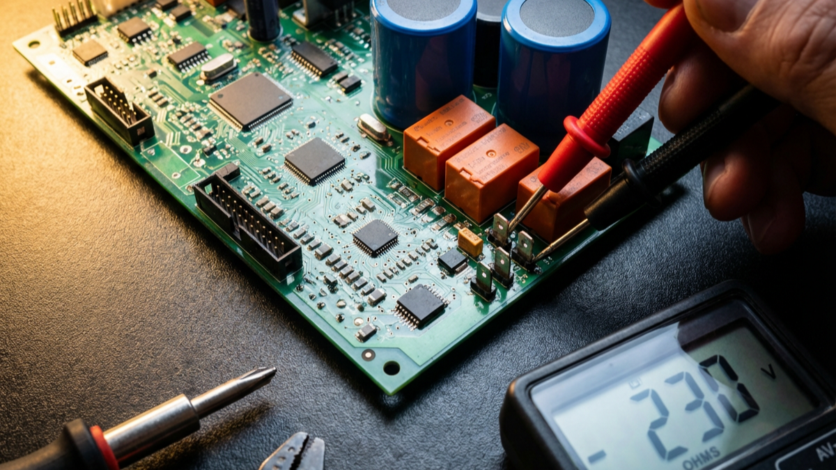
Display errors or blank screens with power present point to failed display drivers on the PCB. Check incoming voltage first; if you have 230V at the board but nothing on the display, the board has failed.
Clicking relays that never energise outputs means the PCB's logic works, but its power circuits have failed. You'll hear the relay coils activate, but connected devices receive no voltage.
Testing Before You Replace
Start with voltage checks at the transformer. Most boilers use a plug-in transformer providing 24V AC to the control board. Measure at the transformer output and again at the PCB terminals. Voltage drop exceeding 2V indicates connection problems, not board failure.
Test each sensor independently. Remove sensor wires from the PCB and measure resistance. A thermistor showing infinite resistance has failed open. One reading zero ohms has failed short. Compare readings to the manufacturer's resistance/temperature chart; most thermistors should read 10-50kΩ at room temperature.
Check the flame-sensing circuit separately. The flame sensor generates a microamp signal when heated by the flame. Measure DC microamps (typically 0.5-5µA) between the sensor wire and ground during operation. No signal means a failed sensor or blocked view of the flame, not necessarily a bad PCB.
Inspect solder joints under magnification. Failed joints appear as cracks around component leads or lifted pads. This happens most often around heavy components like transformers and relays that experience thermal cycling. A single failed joint can cause intermittent operation that mimics a complex electronic failure.
When Voltage Is Present but Nothing Happens
You've confirmed 230V at the board input and 24V at the transformer output. The display shows normal operation. But when the boiler calls for heat, nothing happens.
Test the PCB's output circuits directly. Most boards have test points or you can back-probe connector terminals. During a call for heat, you should measure:
230V at the pump output terminals 24V at the gas valve terminals 230V at the fan output terminals
If the PCB displays the correct status but outputs show no voltage, the board's switching circuits have failed. This typically happens to triacs or relay contacts that handle the higher currents needed by pumps and fans.
If outputs show correct voltage but devices don't run, the problem lies downstream. We find blocked pump impellers, seized fan bearings, and corroded valve coils far more often than failed PCBs in these cases. Quality Grundfos pumps typically signal bearing failure through characteristic humming before complete seizure.
The Gas Valve Confusion
Gas valves fail more often than PCBs, but they present similar symptoms. Both cause a lockout on ignition with flame failure codes. The distinction matters because gas valve replacement costs £80-150 while boiler circuit board replacement runs £200-400.
Test the valve coil resistance. Most gas valves use two coils, one for opening, one for holding. Typical resistance ranges from 80-150Ω per coil. Infinite resistance means a failed coil. Zero resistance indicates a short. Either condition prevents the valve from operating.
Measure the voltage at the valve during ignition. The PCB should send 24V to the valve coils in a specific sequence. If voltage arrives but the valve doesn't open, replace the valve. If no voltage reaches the valve despite the PCB showing normal operation, check the wiring before condemning the board. Honeywell gas valves are common across many boiler models and have well-documented resistance specifications.
Moisture Damage Patterns
Condensate leaks destroy more PCBs than any other single cause. Water creates conductive paths between circuit traces, causing shorts that blow fuses or damage components.
Look for white or green corrosion on the PCB surface. This crystalline deposit forms when moisture evaporates, leaving behind minerals. Even after drying, these deposits remain conductive enough to cause problems.
Check for swollen or burst electrolytic capacitors. These cylindrical components should have flat tops. Bulging or leaking capacitors indicate either moisture damage or age-related failure. A PCB with multiple failed capacitors needs replacement; individual component repair rarely succeeds.
Inspect the conformal coating. Quality boards have a clear protective coating over the circuits. Scratched or worn coating allows moisture penetration. Boards without coating fail faster in damp environments.
Error Code Interpretation
Modern boilers display alphanumeric codes that point towards specific failures. But codes indicate symptoms, not causes.
Flame detection errors (codes like EA, F28, or F29, depending on manufacturer) trigger when the PCB expects to see flame current but doesn't. This happens with failed flame sensors, blocked sensor views, incorrect sensor positioning, or failed detection circuits on the PCB itself. Test the sensor first; it fails more often and costs less.
Overheat codes (E25, F20, or similar) mean either genuine overheating or a failed sensor. The PCB can't distinguish between a 95°C boiler and a sensor falsely reporting 95°C. Measure actual water temperature with an infrared thermometer before replacing anything.
Fan or air pressure codes (F32, E30) indicate the PCB isn't receiving the expected signal from the air pressure switch. This happens when the fan runs too slowly, the pressure switch fails, or the PCB's input circuit fails. Bridge the pressure switch terminals temporarily. If the boiler proceeds with ignition, the switch or fan needs attention, not the board.
Testing PCB Inputs and Outputs Systematically
Create a simple test sequence that isolates the PCB from other components:
Step 1: Disconnect all sensor wires from the PCB. Step 2: Measure the resistance of each sensor independently. Step 3: Reconnect only sensors that test within specification. Step 4: Disconnect all output devices (pump, fan, gas valve). Step 5: Measure the voltage at each output terminal during operation. Step 6: Reconnect only outputs that receive the correct voltage
This process separates sensor failures, wiring problems, and output device failures from actual PCB issues. If sensors test good, outputs show correct voltage, but the boiler still won't fire, the PCB has failed.
When to Repair vs Replace
PCB repair makes sense for boards costing over £300 where the failure involves obvious physical damage, burnt traces, failed relays, or blown capacitors. Several specialist companies offer boiler control board repair services for £80-120 with 12-month warranties.
Replace rather than repair when: Multiple components have failed, The board shows moisture damage across a large area, Solder joints have lifted from the board (delamination), The manufacturer has issued a technical bulletin about known failures, The board is over 10 years old
Programming and Configuration After Replacement
Most modern PCBs require parameter setting after installation. The board needs to know:
Boiler model and maximum output, Pump overrun time, Maximum and minimum modulation rates, Central heating flow temperature, Hot water priority settings
Manufacturer service tools connect via USB or proprietary interfaces. Some boards allow parameter setting through button sequences on the boiler's control panel. Installing a replacement PCB without proper configuration causes poor performance even if the board functions correctly. Danfoss and EPH Controls offer programming interfaces for their compatible control systems.
Record existing parameters before removing a failed board. Many boards display current settings through service menus. Document these values so you can replicate them on the replacement.
Preventing Future PCB Failures
Install the condensate trap correctly. Improperly fitted traps allow condensate to back up into the boiler, where it drips onto the PCB. The trap needs a 75mm water seal and must drain freely.
Maintain proper ventilation around the boiler. PCBs generate heat during operation. Enclosed installations without ventilation cause premature component failure. We've measured PCB temperatures 15-20°C higher in poorly ventilated cupboards.
Address water leaks immediately. A small leak from a pump seal or heat exchanger gasket eventually finds the PCB. Monthly visual inspections catch leaks before they cause expensive damage.
Use surge protection. Lightning strikes and utility switching events send voltage spikes through the electrical supply. A £30 surge protector saves £300 boards. Install protection at the boiler's electrical supply, not just at the main panel.
The Economics of Accurate Diagnosis
A typical PCB costs £200-400. Add travel time, labour, and markup, and the customer pays £350-600 for the replacement. When you replace a board that wasn't actually faulty, you've solved nothing and created a warranty liability.
Spending 15 minutes on systematic diagnosis before ordering parts reduces callback rates by 40% based on our service data. The time invested in proper testing costs less than a single warranty return visit.
Stock common sensors, pressure switches, and gas valve coils. These components fail more often than PCBs and cost less. Having them on the van means you can fix the actual problem on the first visit rather than ordering a PCB you might not need. For a comprehensive range of boiler spares, including sensors and control components, Halstead Spares and other manufacturers offer next-day delivery options.
Making the Right Diagnosis
PCB diagnosis separates competent technicians from parts swappers. The control board manages complex processes, but testing its inputs and outputs follows straightforward logic. Voltage either appears where it should or it doesn't. Sensors either read correctly or they don't.
Most apparent PCB failures trace back to failed sensors, damaged wiring, or faulty output devices. Systematic testing identifies these problems in minutes and costs nothing beyond the time invested. When testing confirms the PCB has actually failed, inputs are correct but outputs are wrong, or the board shows physical damage, replacement makes sense.
The £200-400 you spend on a genuine PCB failure solves the problem permanently. The same money spent on an unnecessary boiler PCB replacement leaves the real fault untouched and guarantees a callback. Know the difference, test methodically, and replace only what has actually failed.
For quality replacement PCBs, control components, and diagnostic support, Heating and Plumbing World stocks genuine manufacturer parts alongside tested pattern alternatives. Should you need technical guidance on PCB diagnosis or replacement procedures, get in touch with our technical team.