
Boiler Pressure Relief Valve Discharge Pipes: Installation
When a boiler's pressure relief valve operates, it releases scalding water at temperatures up to 100°C under significant pressure. Without proper discharge pipe installation, this creates a genuine safety hazard. Between 2019 and 2023, over 300 incidents involving faulty pressure relief systems were reported to UK building control authorities, many linked to incorrect discharge pipe configuration.
The pressure relief valve serves as your boiler's safety mechanism, preventing catastrophic failure when internal pressure exceeds safe limits. The discharge pipe carries this expelled water safely away from people and property. Getting this installation right isn't just about compliance with Building Regulations Part G3; it's about preventing severe scalding injuries and property damage.
Understanding Pressure Relief Valve Function
The pressure relief valve opens automatically when boiler pressure exceeds its set point, typically between 3 and 6 bar depending on your system. This valve releases water to reduce pressure back to safe operating levels. Modern sealed heating systems rely entirely on this mechanism because, unlike older open-vented systems, they lack an expansion cistern to accommodate pressure increases.
Temperature and pressure work together in sealed systems. When water heats, it expands. If the expansion vessel fails or loses its pre-charge, pressure builds rapidly. The relief valve prevents the boiler vessel from rupturing, which would release superheated water explosively into your property.
The boiler pressure relief discharge pipes must handle both the temperature and pressure of this release. Standard plastic waste pipes will deform and fail when exposed to water above 93°C. This is why regulations mandate specific materials and installation methods.
Discharge Pipe Material Requirements
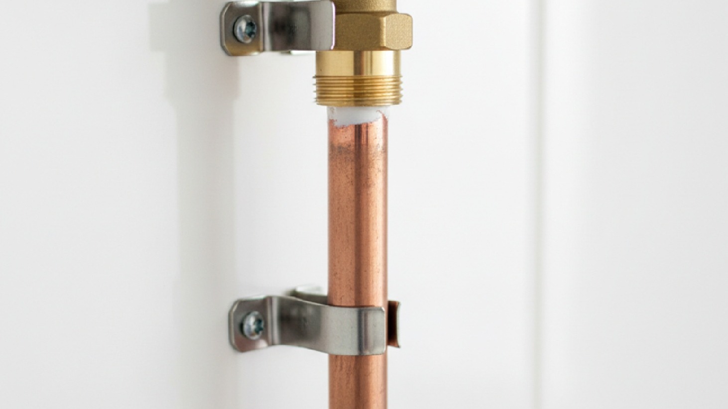
Building Regulations specify copper pipe for the initial 600mm of discharge pipe run from the pressure relief valve. This first section experiences the full temperature and pressure of the expelled water. Copper withstands these conditions without deformation or failure.
Minimum Diameter
The minimum diameter for this copper section is 15mm, though 22mm provides better flow characteristics and reduces back pressure on the valve. 22mm copper significantly reduces the likelihood of valve chattering during discharge events, particularly on higher-capacity boilers.
Material Transitions
After the initial 600mm copper section, you can transition to plastic pipe rated for high-temperature discharge. This must be either copper, stainless steel, or plastic specifically designed for hot water discharge (Class D rated to 110°C minimum). Standard PVC waste pipe is not suitable, even after the copper section.
The transition from copper to plastic requires proper fittings. Use a compression fitting or soldered joint at the copper end, with the plastic connection made according to the manufacturer's specifications. Never force a plastic pipe directly onto copper without appropriate transition fittings, as thermal expansion differences will cause joint failure. Professional pipe fittings ensure reliable connections throughout the discharge system.
Vertical and Horizontal Routing
The pressure relief discharge pipe must route with a continuous fall towards its termination point. A gradient of at least 1:200 prevents water pooling in the pipe, which could freeze in winter and block the discharge path. This calculates as a 5mm drop per metre of horizontal run.
Preferred Routes
Avoid horizontal runs where possible. Vertical drops provide the most reliable discharge path because gravity assists flow and eliminates pooling. When horizontal runs are unavoidable, keep them as short as practical and maintain that minimum gradient throughout.
Support Requirements
Support the pipe adequately to prevent sagging. Copper pipe requires clips every 1.2 metres on horizontal runs and every 1.8 metres on vertical drops. Plastic sections need more frequent support: every 0.5 metres horizontally and every 1.0 metre vertically. Sagging creates low points where water collects and potentially freezes.
Bend Selection
Changes in direction should use swept bends rather than sharp elbows. A 90-degree swept bend creates less resistance to flow than a standard elbow fitting. This matters during discharge events when water volume and pressure are high. Excessive back pressure can prevent the relief valve from seating properly after discharge, causing continuous dripping.
Termination Point Selection
The discharge pipe must terminate in a visible location where discharge is immediately noticeable but where the expelled water cannot cause injury or property damage. This balance is crucial. Hidden terminations mean leaks go undetected; terminations in high-traffic areas create scalding risks.
Ideal Termination Points
External wall positions: Above a drain or soakaway, at least 300mm from ground level to prevent splashing onto people passing below. The pipe should discharge visibly against the wall, not hidden behind guttering or other features. Position it where you'll notice water discharge from windows or when outside.
Into a trapped gully: At a high level, with the pipe end cut at 45 degrees and positioned to prevent debris from entering the pipe. The gully must be external or in a well-ventilated space. Never terminate into internal drainage without a proper air break.
Purpose-built tundish arrangements: For unvented hot water cylinders, can sometimes accommodate boiler discharge pipes, but only if the combined discharge capacity doesn't exceed the tundish specification. Check manufacturer documentation carefully.
Prohibited Termination Locations
Never terminate boiler pressure relief discharge pipes:
- Where discharge could spray onto electrical equipment, gas metres, or other services
- Near windows or doors where people regularly pass
- Into closed drainage systems without proper air breaks
- Into rainwater gutters or downpipes
- Below ground level, where discharge isn't visible
- Near air bricks or ventilation openings
The pipe end should be cut square or at 45 degrees, with no restriction that could impede flow. Don't fit a cap or cover, even to prevent debris entry. A partially blocked discharge pipe creates back pressure that prevents proper valve operation.
Installation Process Step by Step
Connection to Relief Valve
Start at the pressure relief valve itself. Modern boiler systems from Andrews and Halstead have the valve pre-installed, but you'll need to connect your discharge pipe to the valve outlet. This connection typically uses a 15mm or 22mm compression fitting.
Apply PTFE tape or jointing compound to male threads, wrapping clockwise when viewing the thread end-on. Hand-tighten the compression nut, then use a spanner for one and a half additional turns. Over-tightening crushes the olive and can cause leaks; under-tightening obviously leaks immediately.
Copper Section Routing
Route your copper pipe away from the boiler, securing it with clips appropriate to the surface. On masonry, use plastic-lined copper clips with appropriate wall plugs. On timber, standard copper saddles with screws work well. Space clips according to the distances mentioned earlier.
Plan your route to minimise bends and maintain the required fall. Each fitting adds resistance to flow, so fewer is better. If you need to navigate around obstacles, use swept bends and maintain support on either side of each bend.
Material Transition
Where the copper section transitions to plastic, make this joint in an accessible location. If the plastic section ever needs replacement, you want to reach this connection easily. Use a compression-to-plastic transition fitting appropriate for your plastic pipe type.
Plastic Section Continuation
Continue the plastic section to your chosen termination point, maintaining support and gradient. Clip the pipe securely but allow for thermal expansion. Plastic expands significantly when hot water flows through it. Clips should hold the pipe in position without gripping so tightly that expansion causes stress.
Final Termination
At the termination point, ensure the pipe end is clearly visible and positioned to discharge safely. Cut the end cleanly with a pipe cutter rather than a saw, which leaves rough edges that can catch debris. A 45-degree angle helps water discharge cleanly rather than dripping from the pipe end.
Common Installation Mistakes
Undersized Pipe
The most frequent error is using undersized pipe. A 15mm discharge pipe on a larger boiler creates excessive back pressure. When the relief valve opens, restricted flow prevents proper pressure release. This can cause the valve to chatter, repeatedly opening and closing, which damages the valve seat and causes persistent dripping.
Hidden Routing
Running discharge pipes inside cavity walls creates multiple problems. You can't inspect the pipe for leaks, thermal movement can cause joint failure, and any discharge saturates cavity insulation. Always route discharge pipes on the outside of cavity walls or in visible internal locations.
Incorrect Drainage Connections
Terminating pipes into closed drainage without air breaks violates regulations and creates hazards. Sewer gases can travel up the discharge pipe into the boiler, and back pressure from the drainage system prevents proper relief valve operation. Always maintain an air break at termination points.
Inadequate Support
Inadequate support leads to sagging, which creates low points where water pools and potentially freezes. A frozen discharge pipe blocks the relief valve's operation, turning your safety device into a hazard. This particularly affects pipes on north-facing walls or in exposed locations.
Material Incompatibility
Mixing incompatible materials causes joint failures. Standard PVC waste pipe softens and deforms at high temperatures. Pushfit fittings not rated for high-temperature discharge can fail when the relief valve operates. Always verify that every component in your discharge pipe system is rated for the temperatures and pressures involved.
Maintenance and Inspection
Discharge pipes require regular inspection, though they need minimal maintenance if installed correctly. Check the visible termination point quarterly. Look for signs of recent discharge: water staining on walls, damp patches, or corrosion around the pipe end.
Investigating Discharge
If you see evidence of discharge, investigate the cause immediately. Relief valves shouldn't operate during normal boiler function. Discharge indicates either excessive system pressure or a faulty relief valve. Check the boiler pressure gauge. If pressure exceeds 1.5 bar when cold, the system needs attention.
Annual Checks
Inspect pipe supports annually. Loose clips allow sagging, which creates problems over time. Tighten or replace clips as needed. Check that the plastic pipe hasn't deformed where it's exposed to sunlight. UV degradation weakens plastic over time.
Winter Considerations
In winter, check that the pressure relief discharge pipe hasn't frozen. A frozen pipe blocks discharge, preventing the relief valve from protecting your system. Pipes on north-facing walls or in exposed locations are most vulnerable. If freezing is a recurring problem, consider insulating the discharge pipe with waterproof insulation rated for external use.
Valve Testing
Test the relief valve annually by carefully lifting the test lever. This should produce a discharge of water from the termination point. If nothing happens, the valve may be seized or the discharge pipe blocked. If water continues flowing after you release the lever, the valve seat is damaged and needs replacement. Never leave a dripping relief valve unaddressed; it indicates a fault requiring attention.
Integration With System Components
The discharge pipe works as part of your complete heating system safety mechanism. The expansion vessel absorbs normal pressure increases as water heats, preventing the relief valve from operating during routine cycles. When the expansion vessel fails, pressure increases trigger the relief valve discharge.
Quality control components from Honeywell, like pressure gauges and automatic air vents, help maintain correct system pressure. A properly functioning system rarely requires relief valve operation. Regular discharge suggests underlying problems rather than a faulty discharge pipe.
Pump performance affects system pressure. An oversized or incorrectly set circulation pump from Grundfos can create pressure spikes that trigger relief valve operation. Proper system balancing prevents these issues.
Compliance and Documentation
Building Regulations Part G3 governs discharge pipe installation for unvented hot water systems, and these standards represent best practice for boiler relief valve discharge pipes as well. Local building control may require notification for certain installation work, particularly when installing or significantly modifying heating systems.
Record Keeping
Document your discharge pipe installation with photographs showing the route, materials used, and termination point. This documentation proves compliance if questions arise during property sales or insurance claims. It also provides reference for future maintenance or modifications.
If you're working on rented property, ensure landlords receive documentation showing compliant installation. This protects both you and the property owner if issues develop later.
When to Call Professionals
During competent DIY installers can handle discharge pipe installation, certain situations require professional involvement. If your boiler is still under warranty, manufacturer terms may require Gas Safe registered engineer involvement for any work affecting safety components.
Complex Installations
Complex routing through multiple rooms or floors benefits from professional planning. Experienced installers quickly identify optimal routes that maintain required gradients while minimising visible pipework.
System Problems
If your relief valve discharges frequently, this indicates system problems beyond the discharge pipe itself. Professional heating engineers with Danfoss expertise can diagnose whether you're dealing with expansion vessel failure, incorrect system pressure, faulty relief valves, or other issues requiring specialist attention.
Ensuring Safe Operation
Proper discharge pipe installation protects your property and its occupants from scalding injury while ensuring your boiler's safety systems function as designed. The regulations governing these installations exist because of incidents causing harm. Following them isn't bureaucratic box-ticking; it's practical risk management.
Use appropriate materials throughout: copper for the first 600mm, then high-temperature rated pipe to termination. Route with continuous fall, adequate support, and minimal bends. Terminate where discharge is visible but safe. Inspect regularly and address any signs of discharge promptly.
The discharge pipe is your boiler's emergency exit. When pressure exceeds safe limits, this pipe carries dangerous conditions safely away. Installing it correctly means it's ready to perform this critical function whenever needed, potentially preventing catastrophic boiler failure and the injuries or property damage that would follow.
Taking time to get this installation right provides peace of mind that your heating system includes proper safety measures. Whether you're installing a new boiler, replacing an old discharge pipe, or checking an existing installation, these principles ensure your system meets both regulatory requirements and practical safety needs.
For comprehensive guidance on boiler pressure relief discharge pipes and safety components, Heating and Plumbing World stocks professional-grade discharge pipe materials, compression fittings, and safety valves. Quality pressure relief components ensure reliable protection for sealed heating systems. Expansion vessels from Altecnic work alongside properly installed discharge pipework to maintain safe system pressures. For technical advice on pressure relief discharge pipe installation, material selection, or troubleshooting frequent discharge issues, experienced heating engineers can provide support on compliant installation that protects property and occupants.