
Care Home Underfloor Heating: Mixing Shunt Pump Wiring And Floor Temperature Limits
Care homes demand heating systems that balance comfort, safety, and efficiency. Underfloor heating delivers on all three, but only when installed correctly. The mixing shunt pump and floor temperature controls form the critical heart of these systems, yet we regularly find installations that miss fundamental requirements.
Why Care Homes Need Different Temperature Limits
Standard residential underfloor heating runs at 35–40°C floor surface temperatures. Care homes can't use these settings. Residents with reduced mobility sit in chairs for extended periods, their feet in constant contact with the floor. Elderly skin tolerates less heat. Diabetes and circulation issues further reduce heat sensitivity, creating burn risks that wouldn't exist in typical homes.
Heating and Plumbing World provides the technical components needed to adhere to these strict safety requirements.
NHS guidance caps floor temperatures at 27°C in care environments. We set our systems to 24–26°C to build in a safety margin. These floor temperature limits mean larger pipe spacing won't work; we typically use 150mm centres instead of the 200–300mm common in homes. The heat output drops, but resident safety improves dramatically. One facility we worked with in 2023 had inherited a system running at 32°C. Staff reported residents developing reddened feet after afternoon activities. We recalibrated the floor temperature limits to 25°C, increased the heated floor area by 15%, and eliminated the problem.
How Mixing Shunt Pumps Control Temperature
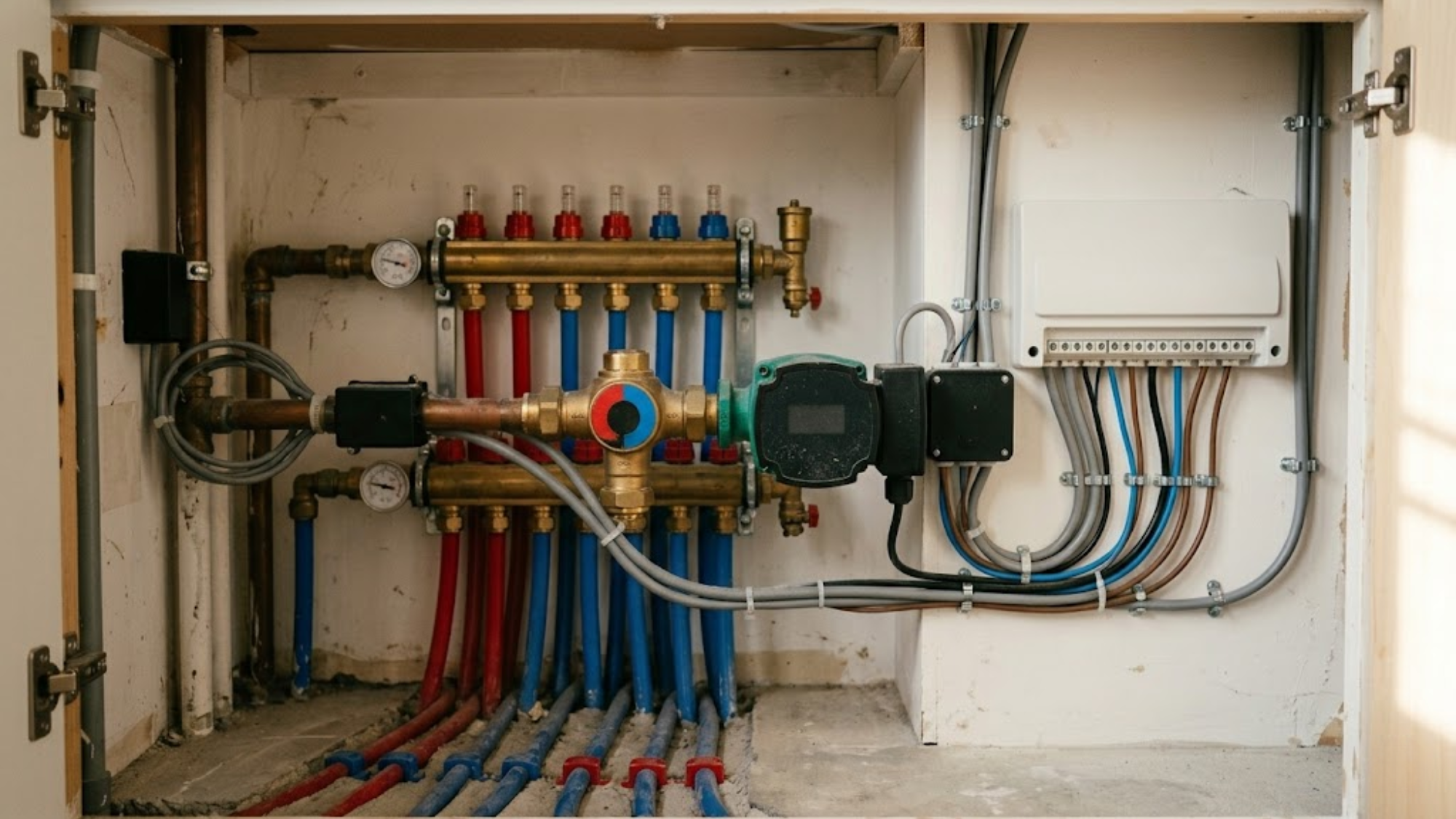
Boilers generate water at 60–80°C for domestic hot water and radiators. Underfloor heating circuits need 35–45°C maximum, and care homes need even less. The mixing shunt pump bridges this gap. The unit contains three key components: a thermostatic mixing valve, a circulation pump, and temperature sensors. Hot water from the boiler enters one side. The mixing valve blends it with cooler return water from the floor circuits. The pump circulates this mixed water through the manifold to the underfloor pipes.
Temperature sensors monitor the mixed water and adjust the valve position. If the water exceeds the setpoint, the valve reduces hot input and increases return water. When the temperature drops, more boiler water enters the mix. This happens continuously, maintaining stable floor temperatures regardless of boiler cycling or outdoor conditions. Integrating high-quality danfoss heating components into the mix ensures that these adjustments remain precise and reliable over the system's lifespan.
Wiring The Mixing Shunt Pump Correctly
Electrical connections determine whether the system responds properly to heating demands. We've seen three common wiring errors that cause problems, particularly regarding zone valve integration and pump sequencing.
- Constant Power Configuration: Some installers wire the pump to run continuously whenever the boiler operates. This wastes energy and wears pump components. The mixing shunt pump should only run when zones call for heat.
- Missing Zone Valve Integration: The pump must activate before zone valves open. Otherwise, valves open with no circulation, creating cold spots. We wire a relay that triggers the pump 30 seconds before any zone valve receives power.
- Inadequate Overrun Settings: When the thermostat satisfies, the pump should continue running for 2–3 minutes to clear residual heat from the pipes.
The correct wiring sequence involves the room thermostat calling for heat, followed by zone valve integration that allows water to circulate only when required. We install a dedicated 230V supply for the mixing unit, protected by a 6A MCB. Adopting a reliable heating system control ensures these sequences are managed without manual intervention.
Setting Up Temperature Limits And Safety Controls
Every care home system needs three temperature limits: floor surface maximum, flow water maximum, and emergency high-limit cutoff. We configure the heating controls to deliver 40°C flow temperature, which produces 24–26°C floor surfaces.
A high-limit thermostat mounts in the manifold, wired to cut power to the pump and close zone valves if flow temperature hits 50°C. This addresses boiler failures or mixing valve malfunctions. While we've never seen this high-limit thermostat trigger in a properly maintained system, it's essential safety infrastructure.
I remember a project in a converted Victorian villa where the previous contractor had bypassed the safety sensors to "solve" a nuisance tripping issue. During a particularly cold February, the mixing valve stuck open, and the floor temperature soared to 38°C in the main lounge. Thankfully, we were on-site for a different repair and caught it before any residents were affected. It was a stark reminder that safety controls are there for a reason; you don't "fix" a trip by removing the protection.
Think of the temperature control system like a thermostat on a kettle. Just as the kettle has a primary switch to boil the water and a secondary safety thermal cut-out to prevent it from melting if the first switch fails, a care home floor needs multiple layers of protection to ensure the heat never reaches dangerous levels.
Manifold Configuration For Multi-Zone Care Facilities
Care homes need extensive zoning. Bedrooms require individual control, whereas day rooms and corridors operate on different schedules. A robust manifold configuration is required to manage these varied demands. We typically install 12–16 port manifolds for facilities under 500m². Larger buildings need multiple manifolds, each serving a wing or floor. Ensuring you have a properly sized heating expansion vessel installation within the system will protect the manifold from pressure spikes as zones open and close.
Each manifold configuration needs flow meters on supply ports and thermostatic actuators on return ports. The flow meters let us verify each circuit receives the design flow rate during commissioning. This is often where a smart trv or similar digital actuator can provide more granular control.
Manifolds mount in accessible locations, usually service cupboards or plant rooms. This manifold configuration must be at waist height, never in ceiling voids or under-floor locations that require tools to access. Staff need to reach isolation valves and drain points for maintenance.
Balancing The System During Commissioning
New installations need proper balancing before handover. This process sets flow rates for each circuit and verifies temperature distribution. We start by running the system at full design temperature with all zones open. Using the manifold flow meters, we adjust each circuit's balancing valve until it achieves the design flow rate. Long circuits need valves more open; shorter circuits need restriction to prevent short-circuiting.
Once flow balances, we measure floor surface temperatures across all areas using infrared imaging. Similar attention to regular central heating components prevents efficiency losses across the wider facility. The final step tests zone control. We close individual zone valves and verify that flow redistributes properly to remaining open zones.
Conclusion
Mixing shunt pump units and temperature controls aren't optional extras in care home underfloor heating; they're the safety systems that prevent resident harm. Proper wiring ensures responsive control, while accurate floor temperature limits prevent dangerous overheating. Every care home project should start with clear safety parameters and a manifold configuration that allows for precise balancing. If you are overseeing a facility upgrade or require technical validation of your current temperatures, get expert advice to ensure your residents remain safe and comfortable.