
Drayton Digistat RF: Wireless Signal Range Troubleshooting And Receiver Binding
The Drayton Digistat RF works brilliantly when the wireless signal connects properly. When it drops, occupants are left with a thermostat that simply cannot control the heating. A frustrated customer wondering why their wireless system constantly fails usually blames the hardware. Engineers have installed hundreds of these units across commercial and residential properties. The communication faults follow highly predictable patterns, and the solutions rely entirely on basic physics. Thorough wireless signal range troubleshooting transforms a temperamental system into a highly reliable heating network.
How The RF System Actually Works
The unit utilizes the precise 868 MHz frequency to communicate seamlessly between the thermostat and the receiver. Professionals sourcing hardware from Heating and Plumbing World understand that this specific band is dedicated to short-range devices, keeping it relatively clear of Wi-Fi router traffic. The thermostat sends temperature readings and heating demands wirelessly. The receiver, wired directly to your boiler, switches the heating on or off based on these exact data packets.
The maximum range in perfect laboratory conditions reaches 30 metres. However, the real-world range heavily relies on the architectural environment. With standard walls, interference, and typical building materials, you often see 15 to 20 metres or less. The system absolutely needs bidirectional communication. The thermostat must reach the receiver, and the receiver must clearly acknowledge receipt. If either signal fails to penetrate the environment, the connection drops entirely.
Signal Range Problems And What Causes Them
Building materials block and deflect signals differently. A standard single brick wall might reduce your effective range by 20%. Add foil-backed insulation panels, metal stud walls, or heavy reinforced concrete, and you have instantly cut that 30-metre theoretical range down to under 10 metres.
Heavy RF module interference from competing devices creates massive invisible noise. Wireless doorbells, legacy security systems, and some baby monitors utilize remarkably similar frequencies. An environment previously showing a perfect signal can degrade immediately if a neighbour installs a competing high-power wireless device.
Additionally, low battery voltage in the thermostat heavily reduces the raw transmission power. The unit might show plenty of battery life remaining on the digital display, but weak cells simply cannot push the signal through dense obstacles. Always replace the batteries before commencing any diagnostic teardowns. Even a heavily shielded combi boiler can block a weak transmission if the receiver sits directly behind it.
Testing Signal Strength In The Real World
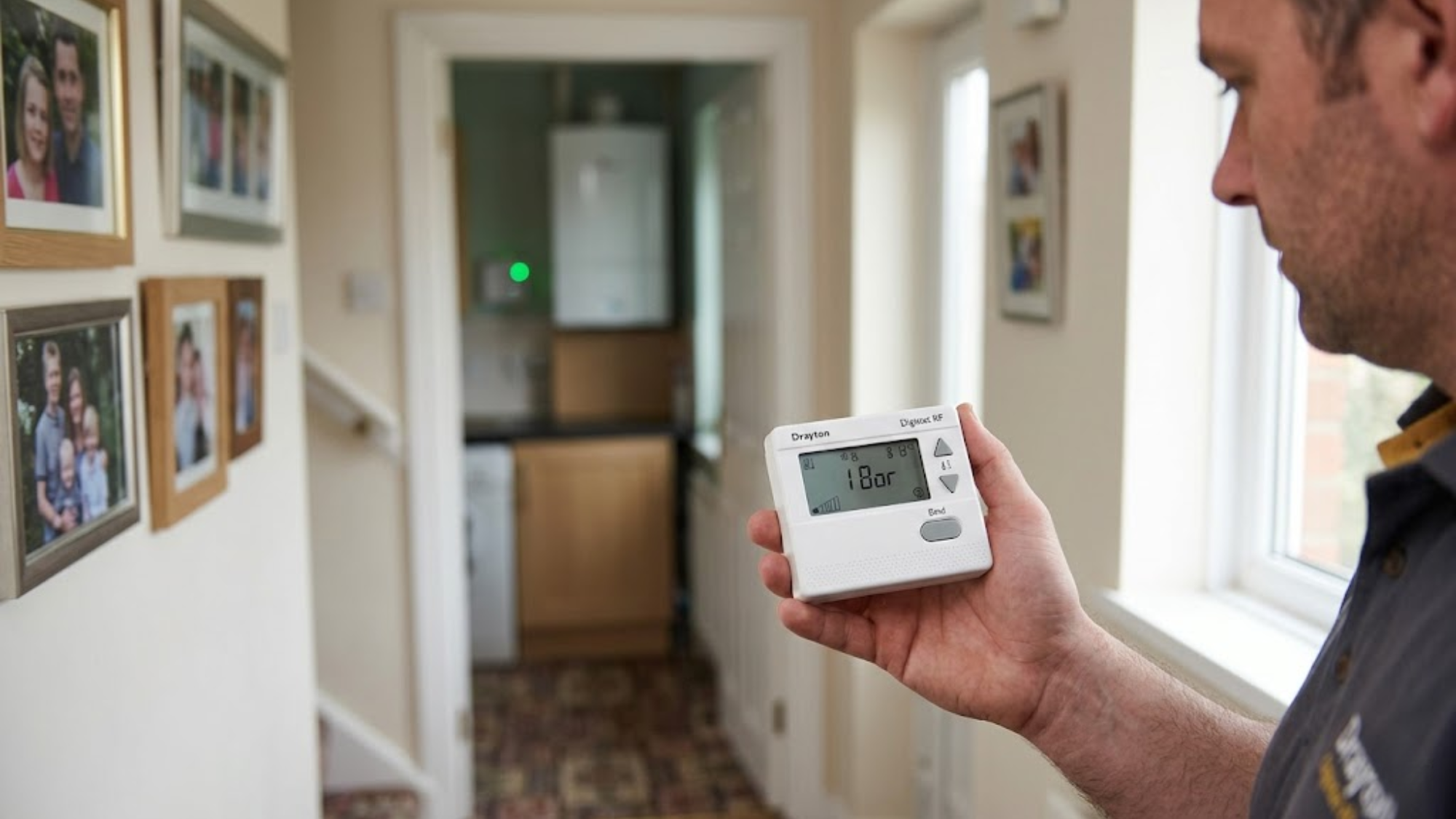
You must test the actual transmission strength before declaring the hardware faulty. Press and hold the thermostat's mode button for 5 seconds. The display shows the signal strength as vertical bars, functioning identically to a mobile phone indicator.
Four bars indicate an excellent connection requiring no action. Three bars show adequate strength, but you should monitor the system for unexpected drops. Two bars present a marginal connection that is highly likely to fail during peak interference times. One bar or a flashing signal icon means you have a completely unreliable connection requiring immediate attention.
Walk around with the thermostat during this testing phase to physically map out the property. You will quickly find dead zones and strong zones. For a standard home radiator system, sometimes moving the receiver just 2 metres makes the absolute difference between a one-bar failure and a four-bar success.
Fixing Range Issues With Proven Solutions
Relocate the receiver first. This simple action solves 60% of the transmission problems engineers encounter in the field. Move it far away from metal enclosures, heavy boiler bodies, and dense structural wall sections. Mount it on a wall directly facing the thermostat location if possible.
On a recent residential installation, an apprentice mounted the receiver directly behind a massive steel casing in the airing cupboard. The signal completely dropped every time the unit fired. Simply moving the receiver one metre to the adjacent plasterboard wall instantly restored a perfect four-bar signal, proving that line-of-sight obstruction destroys connectivity.
Change the thermostat mounting location if moving the receiver proves impossible due to tight cabling. Interior walls work far better than exterior walls because they contain less insulation and lack foil backing. Upgrading to a highly reliable wireless thermostat requires careful placement to maximize the transmission path.
The Receiver Binding Sequence
Binding physically connects a specific thermostat to a specific receiver. You must execute the correct receiver binding sequence when installing new equipment, after replacing either component, or if the connection completely drops from memory.
First, ensure the receiver has a solid 230V power supply. The green power LED should illuminate steadily. Second, press and hold the receiver's binding button for 5 seconds. The red LED starts flashing rapidly. You now have exactly 60 seconds to complete the pairing. Third, on the thermostat, press and hold both the up and down temperature buttons simultaneously for 5 seconds. The display will show "bind" or reveal a linking icon. Finally, the receiver's red LED changes from rapid flashing to steady, then turns off completely.
The green LED on the receiver flashes briefly whenever it receives active data signals from the thermostat. Test this by setting a temperature high above the current room ambient to trigger a heating demand. The receiver should click audibly.
Troubleshooting When Binding Fails
If the receiver LED doesn't flash when you press the pairing button, immediately check the main power supply. Verify the internal fuse and test the mains outlet with a multimeter. If the thermostat doesn't show the bind menu, replace the batteries and try the button combination again using firmer, simultaneous presses.
Think of RF module interference like trying to shine a flashlight through a dense, foggy room. The light might penetrate a short distance, but heavy obstacles like metal cabinets or dense foil insulation will reflect the beam entirely, leaving the receiver completely in the dark.
If the receiver LED flashes but never goes steady, the signal is too weak during the initial pairing. Move the devices much closer together. Attempt the sync with both units sitting in the exact same room before permanently mounting the heating controls to the wall.
Multiple Thermostats And Zone Control
The standard RF3 receiver actively supports up to three wireless thermostats for advanced zone control. Each thermostat binds to the exact same receiver but commands different zones through completely separate relay outputs.
Bind the first thermostat using the standard process outlined above. For the second thermostat, press the receiver's binding button twice rapidly within two seconds. The red LED flashes in a different, distinct pattern. Follow the same thermostat syncing steps. For the third thermostat, press the button three times rapidly.
This multi-zone capability pairs excellently with modern smart trv hardware to precisely control temperatures across large floors. However, adding a third thermostat to a system that has run with two for several months sometimes requires unbinding all the units and starting the sync completely fresh to clear corrupted memory banks.
Signal Dropout After Successful Installation
A system that worked flawlessly for months but then suddenly starts dropping the signal always points to environmental changes rather than spontaneous equipment failure.
Investigate any new interference sources. Neighbours installing new wireless equipment, newly activated security systems, or even cheap LED bulbs with noisy RF drivers can cause massive issues. Building modifications also destroy signal paths. If the homeowner added new wall insulation, installed heavy metal shelving between the devices, or relocated a large appliance, the signal path is likely blocked. Battery degradation happens slowly. Voltage drops gradually, heavily reducing the transmission power over weeks. Always replace the batteries every twelve months regardless of whether the low battery warning actually appears.
Range Extender Alternatives
Drayton does not manufacture official repeaters for this specific system, so you have two realistic options for extremely difficult installations.
The first is deploying a wired alternative. Run a physical cable from the boiler directly to the thermostat location. This absolutely solves all range and interference issues permanently. The second option involves moving the receiver to an alternative central location with extended boiler wiring. Instead of mounting the receiver directly at the boiler, mount it at a midpoint between the boiler and the thermostat. Run longer, protected cables back to the heat engine. This effectively halves the distance the 868 MHz frequency needs to travel through the air.
Conclusion
The Drayton Digistat RF delivers highly reliable wireless heating control when the signal strength and the pairing sequences are properly addressed. Most transmission issues stem strictly from building materials blocking the waves or poor receiver positioning. Both issues are completely fixable through simple hardware relocation rather than undertaking an expensive equipment replacement.
Always test the exact signal strength before committing to a permanent installation, position the receivers far away from dense metal enclosures, and follow the exact receiver binding sequence to guarantee success. When unpredictable problems occur in existing installations, start the diagnosis with fresh batteries and walk-testing before assuming the circuit board has failed. The system works flawlessly within its 15-20 metre real-world range. If you require assistance identifying persistent signal blockers or need advice on alternative wired systems, contact our support team for dedicated hardware guidance.