
Fire Valve Installation for Oil Tanks: Safety Requirements
Oil tank fires represent one of the most dangerous heating system emergencies in domestic and commercial properties. When heating oil ignites, it burns intensely, spreads rapidly, and produces thick, toxic smoke that can overwhelm occupants within minutes. A properly installed fire valve creates a critical barrier between the fuel source and the flames, automatically cutting off the oil supply when temperatures spike.
Properties where fire valves were either missing entirely, incorrectly positioned, or installed with the wrong specifications demonstrate consequences ranging from failed insurance claims to devastating property damage. Understanding the technical requirements for fire valve installation isn't just about compliance with building regulations; it's about creating a system that actually functions when seconds count.
What Fire Valves Actually Do
Fire valves operate on a simple but effective principle: they contain a fusible link that melts at specific temperatures, typically between 68°C and 82°C. When this link melts, a spring-loaded mechanism slams shut, stopping oil flow to the burner. This happens automatically, requiring no human intervention or electrical power.
The valve sits in the oil supply line between the tank and the heating appliance. During normal operation, it remains fully open, allowing unrestricted fuel flow. The moment the ambient temperature around the valve exceeds its rated threshold, the mechanism activates. This design addresses the fundamental problem with oil fires: once they start, they're self-sustaining. The burning oil creates heat, which vaporises more oil, which feeds the flames. Breaking this cycle by stopping fuel supply is the only effective intervention.
Oil tank fire valves differ fundamentally from standard ball valves or gate valves. Standard valves require manual operation, which assumes someone is present, aware of the fire, and able to safely access the valve location. In fire conditions, these assumptions rarely hold true. Smoke typically renders the boiler room inaccessible within two to three minutes of ignition.
Regulatory Framework and Standards
Building Regulations Approved Document J sets out requirements for oil-fired heating installations in England and Wales. Similar standards apply across Scotland and Northern Ireland through their respective building control systems. These regulations mandate fire valve installation in specific circumstances, but the technical standards they reference provide the detailed specifications installers must follow.
BS 5410-1:1997 remains the primary standard for oil-fired heating installations in domestic properties. It requires fire valves on all oil supply lines unless the tank sits outside with a fire-resistant wall between the tank and the appliance. Even then, many insurance companies insist on fire valve installation as a condition of coverage.
The valve itself must comply with BS 799-5, which specifies construction standards, operating temperatures, and performance criteria. Only valves bearing this certification provide the reliability needed during an emergency. Quality heating components from manufacturers like Danfoss meet these exact specifications, ensuring installations comply with both regulatory and insurance requirements.
Fire valve regulations UK expand for commercial properties under the Regulatory Reform (Fire Safety) Order 2005. This legislation places responsibility on the "responsible person", typically the building owner or manager, to conduct fire risk assessments and implement appropriate mitigation measures. For premises with oil-fired heating, this assessment almost always identifies fire valve installation as a necessary control measure.
Positioning Requirements That Actually Matter
The most common installation error involves valve positioning. Regulations specify that oil tank fire valves must be located "in the same fire compartment as the appliance", but what does this actually mean in practice?
The valve must sit where it will experience the heat from a fire starting at or near the boiler or burner. Placing it in a separate room, outside the building, or in a location shielded from the appliance defeats its purpose entirely. If fire breaks out in the boiler room, the valve must detect that temperature rise and respond.
Specifically, the valve should be:
Within the same room as the heating appliance, not in an adjacent space or corridor. Fire doors and walls create thermal barriers that delay heat transfer, potentially allowing a fire to establish before the valve activates.
Within 2 metres of the appliance, measured along the pipe run. This proximity ensures rapid thermal response. Some installers place valves immediately adjacent to the oil entry point into the building, which might be 5 or 10 metres from the boiler. This creates a dangerous delay between fire ignition and fuel cut-off.
Accessible for inspection and testing, but not so exposed that accidental damage becomes likely. The valve needs annual inspection to verify the fusible link hasn't corroded or been painted over (paint insulates the link, raising its activation temperature).
Downstream of any filters, so debris can't prevent the valve from closing completely. A partially closed fire valve still allows fuel through, rendering it ineffective.
Tank installations vary significantly between properties. For external tanks feeding internal boilers from manufacturers like Andrews or Morco, the fire valve must be inside the building, within the boiler room. The external isolation valve (required at the tank outlet) serves a different purpose; it allows safe maintenance and tank removal, but won't respond to fire conditions inside the building.
Installation Process and Technical Considerations
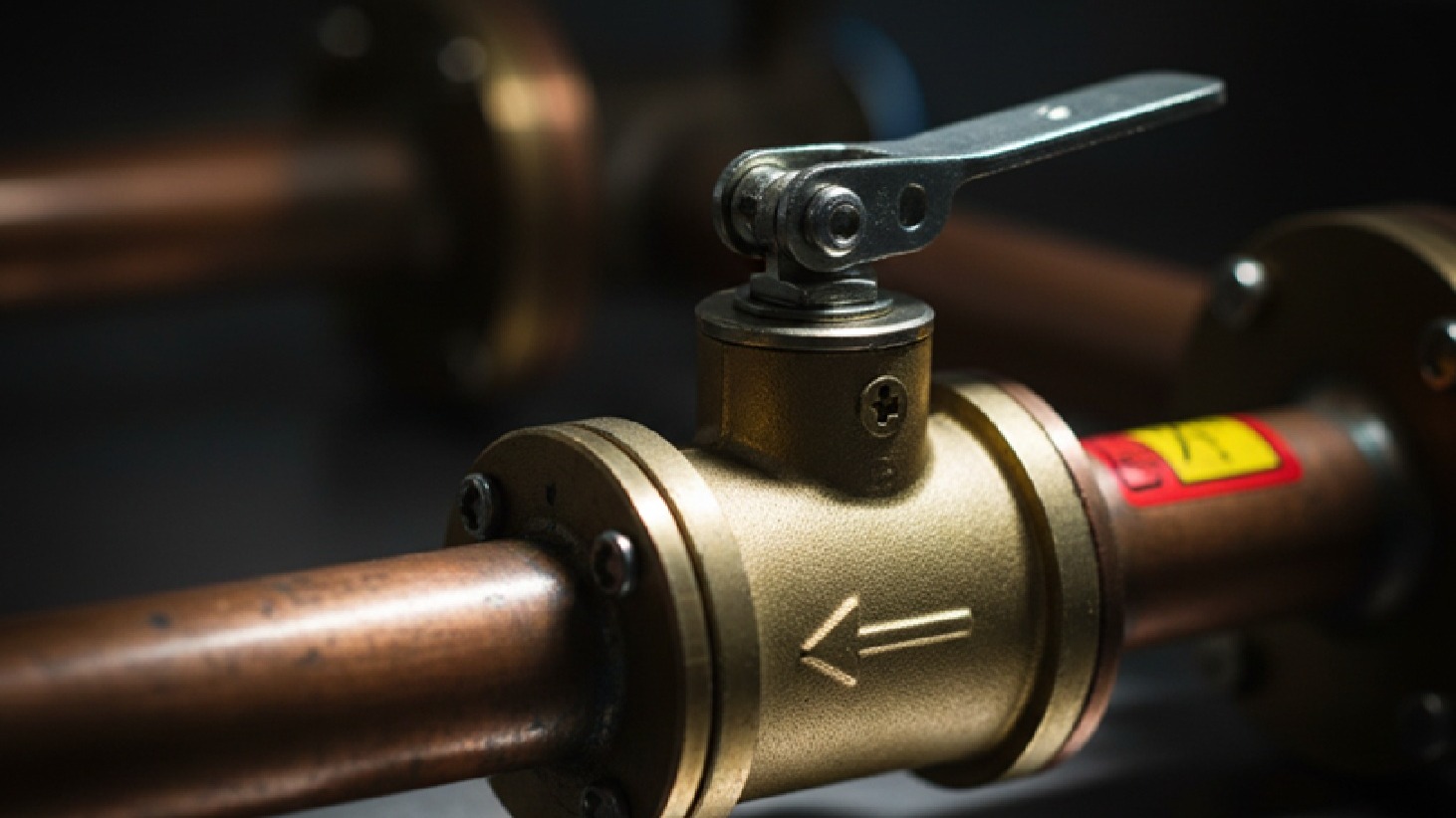
Fire valve installation requires more precision than standard plumbing work. The orientation matters: most valves are directional, with flow arrows marked on the body. Installing them backwards prevents proper closure or creates excessive pressure drop during normal operation.
Thread preparation determines long-term reliability. PTFE tape rather than hemp and paste works best for these connections, as hemp can shed fibres that lodge in the valve mechanism. Apply tape in the direction of thread rotation (clockwise when viewing the male thread end-on), using 3-4 wraps for 10mm fittings, 4-5 wraps for 15mm. Quality pipe fittings and connectors ensure reliable connections throughout the oil supply system.
Tightening torque needs careful control. Over-tightening distorts the valve body, potentially jamming the mechanism. Under-tightening risks leaks. Use a torque wrench set to manufacturer specifications, typically 25-30 Nm for 10mm compression fittings, 30-35 Nm for 15mm.
The pipe run between the fire valve and appliance should be as short as practical, with minimal bends. Each elbow adds flow resistance, and the residual oil in this section will continue feeding the fire after the valve closes. A 3-metre run of 10mm copper pipe holds roughly 235ml of oil, enough to sustain flames for several minutes.
Support the pipework independently on both sides of the valve. Fire valves aren't designed to carry structural loads from the pipe system. Unsupported pipes can sag over time, creating stress on the valve body that interferes with proper closure. Use pipe clips within 300mm of each side of the valve.
For systems using reliable oil pumps from Danfoss or circulation pumps from Grundfos, consider the interaction between pump pressure and valve operation. Some older fire valves struggle to close against high differential pressures. Modern valves incorporate stronger springs to overcome this, but checking compatibility prevents failures.
Testing and Commissioning Procedures
Installing a fire valve means nothing if it doesn't work when needed. Commissioning tests verify mechanical operation before the system goes live. This isn't about simulating fire conditions, you're checking that the mechanism moves freely and seals completely.
Start with a visual inspection. Check that the fusible link is intact, properly seated, and not painted or corroded. Verify the flow direction arrow aligns with actual oil flow. Confirm all pipe connections are tight and leak-free.
Mechanical testing involves manually operating the valve closure mechanism. Most fire valves include a test button or lever that allows temporary closure without damaging the fusible link. Press this button while observing the valve body. You should hear a distinct click as the mechanism engages, and the lever should offer firm resistance.
With the valve closed, check for complete fuel cutoff. Start the burner motor (not the burner itself, you're testing fuel flow, not creating flames). No oil should reach the nozzle. If the burner attempts ignition without successful fuel delivery, the fire valve is functioning correctly. If the burner fires normally, the valve isn't sealing completely, reject it and fit a replacement.
Release the test mechanism and verify the valve reopens fully. Oil flow should resume immediately. Any hesitation or partial opening indicates problems with the spring mechanism or binding in the valve body.
Documentation forms a critical part of commissioning. Record the valve model, serial number, installation date, and fusible link temperature rating. Photograph the installation showing valve position relative to the boiler, pipe routing, and support arrangements. This documentation proves invaluable for insurance purposes and guides future maintenance.
Annual testing should follow the same procedure. Many installers neglect this, assuming that a valve that worked when new will continue working indefinitely. Corrosion, paint overspray, and mechanical wear all compromise operation over time. The ten minutes needed for annual testing prevent potentially catastrophic failures.
For commercial installations with building management systems, consider integrating fire valve status monitoring. Some modern fire valves incorporate electrical contacts that signal when the valve has closed. This information feeds into alarm systems, alerting building managers and potentially triggering automatic responses like activating suppression systems or notifying emergency services.
Selecting the Right Fire Valve Specification
Not all fire valves suit all applications. Matching the valve to your specific installation ensures reliable operation and regulatory compliance according to the UK fire valve regulations UK.
Flow capacity must match or exceed your burner's maximum fuel consumption rate. Undersized valves create excessive pressure drop, starving the burner and causing incomplete combustion, sooting, and efficiency losses. Check the burner manufacturer's specifications for fuel flow rate (typically expressed in litres per hour or kg/h), then select a valve rated for at least 20% above this figure to provide margin for pressure variations.
Connection type depends on your existing pipework. Compression fittings suit copper pipe installations and allow easier future removal. Threaded connections work for steel pipework but require careful thread preparation. Some valves offer both options on different inlet/outlet combinations. Quality plumbing fittings from Polypipe complement proper fire valve installation.
Fusible link temperature rating should match your operating environment. For standard domestic boiler rooms with normal ambient temperatures (15-25°C), 68°C links provide appropriate safety margins. Commercial plant rooms with higher ambient temperatures may require 82°C links to prevent nuisance activation during normal operation.
Certification and approvals matter enormously. Only valves bearing BS 799-5 certification meet UK regulatory requirements. Some imported valves carry equivalent European certifications (EN standards) that UK building control authorities accept, but verify acceptance with your local authority before installation.
Brand reputation reflects long-term reliability. Fire valves might sit unused for decades, but they must work perfectly when called upon. Established manufacturers subject their products to extensive testing and maintain consistent quality control.
Insurance Implications and Risk Management
Insurance companies take fire valve requirements seriously. Many policies explicitly require fire valve installation on oil-fired heating systems as a condition of coverage. Properties lacking compliant oil tank fire valves may find claims denied entirely, even if the fire started from an unrelated cause.
The logic is straightforward: fire valves represent a fundamental risk control measure. Their absence suggests broader maintenance and safety deficiencies that increase overall risk. Insurers view properties without fire valves as higher-risk propositions, reflected in either higher premiums or coverage limitations.
Before making any changes to oil heating systems, notify your insurance company. This applies to new installations, system modifications, and even temporary situations where a fire valve might be removed during maintenance. Some policies require written confirmation that work has been completed to comply with standards before coverage resumes.
Keep all documentation related to fire valve installation and maintenance. This includes:
- Original installation certificates showing compliance with BS 5410-1
- Annual inspection records documenting fusible link condition
- Photographs showing correct positioning and installation details
- Receipts for replacement parts and maintenance work
This documentation proves invaluable during claims processing. Insurance adjusters need evidence that the system met requirements at the time of any incident. Properties with comprehensive documentation receive faster claim processing and fewer challenges to coverage.
Fire Valves in Different Property Types
Domestic properties typically use simpler fire valve installations. Single boiler systems with external tanks need one fire valve positioned within the boiler room, close to where the oil line enters the appliance. The valve protects against fires originating at the boiler itself, the most common ignition point in these systems.
Commercial properties present more complex scenarios. Multiple boilers, larger fuel consumption rates, and longer pipe runs require careful system design. Each boiler should have its own fire valve, positioned within 2 metres of that specific appliance. Shared fuel lines supplying multiple boilers need fire valves on each branch, not just on the main supply line.
Industrial installations with very high fuel flow rates might need multiple parallel fire valves to achieve sufficient flow capacity without excessive pressure drop. These systems require specialist design input to ensure all valves close simultaneously during an emergency.
Listed buildings and heritage properties face additional constraints. Planning authorities may restrict visible pipework modifications, requiring creative solutions to achieve compliant fire valve installation without compromising architectural features. In these situations, working with heating engineers experienced in conservation projects prevents costly mistakes and planning conflicts.
Integration with Complete Heating Systems
Fire valves work alongside other critical safety components to protect oil-fired heating systems. Understanding these relationships ensures comprehensive protection.
Quality expansion vessels from Altecnic maintain stable system pressure, preventing pressure-related issues that might interfere with fire valve operation. Proper system pressurisation ensures valves can close completely against working pressure.
Hot water cylinders from manufacturers like Gledhill and Kingspan integrate with oil-fired heating systems. Ensuring fire valves protect the primary heat source safeguards the entire installation.
Heating controls from EPH Controls and Honeywell manage system operation efficiently while fire valves provide emergency protection. Both contribute to safe, reliable heating.
Final Considerations for Safe Installation
Fire valve installation represents a critical safety measure that protects property and lives. The technical requirements exist for sound reasons based on decades of fire investigation data and engineering analysis. Cutting corners or approximating standards creates genuine risks with potentially devastating consequences.
Every installation is unique. Tank positions, pipe routes, boiler room layouts, and existing system configurations all influence the optimal approach. What works perfectly in one property might be completely inappropriate in another. This is why fire valve installation should always involve qualified heating engineers with specific experience in oil-fired systems.
The components themselves matter. Using properly certified valves from reputable manufacturers ensures the device will actually function when needed. Budget alternatives lacking proper certification might save a few pounds initially, but they represent false economy when measured against potential fire damage costs.
Regular maintenance keeps these safety systems functional. Annual inspections catch deterioration before it compromises performance. Replacing fusible links on schedule ensures activation temperatures remain within design parameters. Documentation proves compliance and supports insurance coverage.
Fire valves work. When correctly specified, properly installed, and regularly maintained, they provide reliable protection against oil fire escalation. They're not optional extras or regulatory box-ticking exercises; they're essential safety devices that have prevented countless catastrophic fires across UK properties.
The investment in compliant fire valve installation is modest compared to the value of the property and heating system it protects. More importantly, it's trivial compared to the irreplaceable value of the lives that depend on these systems functioning safely every day. Getting the installation right the first time creates peace of mind that lasts for decades.
For quality oil tank fire valves that comply with fire valve regulations UK, Heating and Plumbing World supplies certified products suitable for both domestic and commercial oil heating installations. If you need specific advice on fire valve selection or installation requirements, get in touch for expert guidance ensuring your installation meets all safety and regulatory standards.