
Gas Valves: Identifying When Replacement Is Needed
Gas valves fail without warning, and the consequences range from complete heating system shutdown to dangerous gas leaks. Thousands of faulty gas valves have been diagnosed across commercial and residential systems, and the patterns are consistent: specific symptoms appear weeks or even days before total failure.
What follows explains the assessment of gas valve condition, the testing methods that reveal hidden faults, and when replacement becomes the only safe option.
How Gas Valves Control Combustion
Gas valves regulate fuel flow to burners through electromagnetic controls. When the thermostat signals for heat, the valve receives voltage (typically 24V AC in residential systems), energising a solenoid or operator that opens the gas pathway. The valve closes when the voltage stops, cutting the fuel supply.
Three main types dominate heating systems:
Standing pilot valves maintain a small flame continuously, using a thermocouple to prove pilot presence before allowing main burner gas flow. These older designs consume gas 24/7 but offer simple, reliable operation.
Intermittent pilot valves ignite the pilot only when heating is needed, then open the main valve once the pilot ignites. This reduces gas waste while maintaining proven ignition reliability.
Direct ignition valves eliminate the pilot entirely, using hot surface igniters or spark ignition to light main burners directly. Modern systems favour this approach for maximum efficiency.
Each design fails differently. Standing pilot systems typically lose the thermocouple signal. Intermittent pilot valves develop timing issues between the pilot and main valve opening. Direct ignition systems show operator coil failures or stuck valve bodies.
Early Warning Signs of Valve Deterioration
Gas valve problems announce themselves through combustion irregularities before complete failure occurs. These symptoms are tracked during routine maintenance:
Delayed ignition creates a distinctive "boom" when burners finally light. Gas accumulates in the combustion chamber during the delay, then ignites all at once. This indicates the valve opens too slowly, often due to debris on the seat or weakened operator springs. Each delayed ignition stresses the heat exchanger and increases crack risk.
Short cycling, where burners fire for 30-90 seconds then shut off, suggests the valve closes prematurely. Voltage is measured at the valve during operation. If the supply voltage remains constant but the valve closes, internal operator failure is confirmed. Ambient temperature affects this: valves that cycle properly in mild weather but fail in extreme cold have contaminated operators that stiffen.
Flame rollout appears as flame extending beyond the burner box, often triggering rollout switches. While multiple causes exist (blocked vents, cracked heat exchangers), a gas valve delivering excessive flow creates this condition. Manifold pressure measurements above manufacturer specifications by 0.5" W.C. or more indicate valve seat erosion, allowing overfiring.
Pilot outages in standing pilot systems point to either thermocouple failure or valve electromagnet weakness. Thermocouple output is tested (should generate 25-35 millivolts), then the valve's dropout voltage is measured. If the thermocouple generates adequate voltage but the pilot won't stay lit, the valve's electromagnetic coil has degraded and won't hold with normal thermocouple output.
Gas odour near the appliance indicates external leakage, usually from deteriorated gaskets between valve sections or at pipe connections. Soap solution is applied to all valve joints during annual maintenance; even small bubbles require immediate attention. Internal leakage (valve seat not sealing) shows as continuous pilot outages or burners that won't fully extinguish.
Testing Procedures That Reveal Hidden Faults
Visual inspection misses most gas valve problems. Specific tests evaluate valve condition:
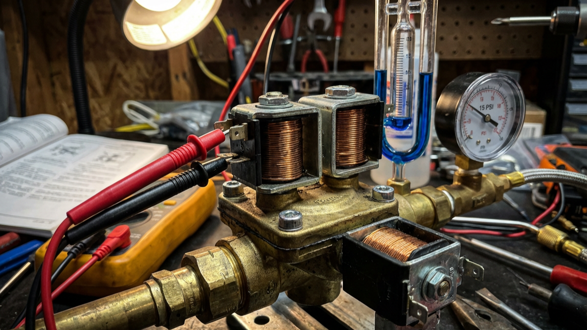
Voltage testing confirms the valve receives proper operating power. Voltage is measured at the valve terminals with the thermostat calling for heat; it should read within 10% of rated voltage (typically 22-26V AC for 24V systems). Low voltage indicates transformer issues or wiring resistance, not valve failure. If the voltage is correct but the valve doesn't open, internal operator failure is confirmed.
Resistance testing evaluates the operator coil condition. With power off and the valve disconnected, coil resistance is measured across the terminals. Specifications vary by model, but residential valves typically show 40-150 ohms. Infinite resistance means open coil (definite failure). Zero resistance indicates a shorted coil (also requires replacement). Readings within range but at the extreme ends suggest deterioration.
Manifold pressure testing reveals whether the valve regulates properly. A manometer is installed at the manifold pressure tap with burners firing. Pressure should match manufacturer specifications exactly (commonly 3.5" W.C. for natural gas, 10-11" W.C. for propane). Pressure more than 0.3" W.C. off specification indicates internal regulator failure or the wrong valve for the fuel type.
Inlet pressure testing checks the supply pressure reaching the valve. Measurement occurs at the inlet tap with all appliances firing. Natural gas should show 6-8" W.C., propane 11-13" W.C. Low inlet pressure causes ignition problems that mimic valve failure but actually indicate meter or regulator issues.
Leak testing finds external and internal leaks. For external leaks, a soap solution is applied to all valve joints and connections with gas on but burners off; any bubbles require immediate repair. For internal leaks (valve seat not closing), the manual valve upstream is shut, the burner supply line is removed, and gas flow is checked with the system off. Any gas smell or pressure indicates seat failure.
When Repair Makes Sense Versus Replacement
Some gas valve issues allow repair, but most require complete replacement. These decision criteria apply:
Repairable conditions include loose electrical connections, corroded terminals (cleaned with contact cleaner), and external gasket leaks on multi-section valves. Valve sections have been successfully resealed using the manufacturer's gasket kits. This works for combination gas valves, where the pressure regulator section can be separated from the operator section.
Replace immediately for these conditions:
- Any internal gas leak (valve seat erosion)
- Operator coil failure (open or shorted)
- Manifold pressure that can't be adjusted to specification
- Cracked valve body or stripped ports
- Water damage or corrosion affecting internal components
- Valves more than 15 years old showing any malfunction
Age matters significantly. Gas valves manufactured before 2000 used different materials and designs from current models. Replacement rather than troubleshooting is recommended for valves over 20 years old, even if they still function; the risk of sudden failure increases sharply after this point.
Safety shutoff valves in commercial systems require a different analysis. These valves include redundant safety features and supervisory circuits. When a safety lockout occurs, a determination is made whether the valve itself failed or whether it correctly responded to an unsafe condition (flame rollout, high limit, etc.). Many "valve failures" are actually the valve correctly preventing operation due to other system faults.
Selecting the Correct Replacement Valve
Gas valve replacement requires exact specification matching. Installing an incorrect valve creates safety hazards and code violations.
Critical specifications to verify before ordering:
- Fuel type: Natural gas and propane valves are NOT interchangeable. The orifices, springs, and regulator settings differ completely
- Voltage: 24V, 120V, or 750mV (millivolt systems). Wrong voltage prevents operation or destroys the valve
- Connection size: 1/2" and 3/4" pipe threads are the most common. Adapters are never acceptable
- Pressure regulation: Single-stage or two-stage, with specific outlet pressure ratings
- Operator type: On/off, modulating, or ratio-regulated for combination systems
- Safety features: Some applications require valves with integral pressure switches or proof-of-closure switches
The existing valve's model number should be cross-referenced with manufacturer specifications rather than assuming compatibility based on appearance. Valves that look identical may have different internal regulation or safety features.
Universal replacement valves exist for common residential applications, but they're avoided in commercial systems or specialised applications. A properly specified OEM valve costs £40-120 more than a universal valve but eliminates compatibility issues and provides manufacturer support.
Combination gas valves integrate multiple functions (gas valve, pressure regulator, pilot valve, safety shutoff) in one assembly. When one component fails, the entire assembly requires replacement; individual sections aren't serviceable. Common combination valves are stocked for emergency replacements since heating system downtime in winter creates urgent situations.
Installation Requirements That Prevent Future Problems
Proper installation extends valve life and ensures safe operation. These procedures apply:
Pipe preparation removes debris that damages valve seats. All pipe threads are cleaned with a wire brush, pipe dope is applied only to male threads (never female threads, where compound can enter the valve), and dope is kept back from the first two threads. Gas lines are blown out before connecting the valve. Construction debris and pipe scale are the primary causes of premature valve failure.
Orientation matters for many valves. Most mount with the operator (electrical section) upright, but some designs allow horizontal mounting. Orientation requirements are verified in the installation manual; incorrect mounting can trap condensation in the operator housing, causing electrical failures.
Electrical connections require proper terminals and wire sizing. Crimp-on spade terminals are used rather than wrapping bare wire around screws; this provides consistent contact and prevents wire breakage. For valves in damp locations, dielectric grease is applied to terminals before connection.
Pressure testing confirms no leaks before operation. The gas line is pressurised to working pressure (typically 1/2 PSIG for residential, higher for commercial), soap solution is applied to all connections, and observation occurs for 15 minutes. Any pressure drop or bubbles require investigation before proceeding.
Manifold pressure adjustment optimises combustion. With the system running, the regulator screw is adjusted while monitoring manifold pressure until it matches specifications exactly. This adjustment affects efficiency, flame characteristics, and heat exchanger longevity; it's not optional.
Maintenance Practices That Extend Valve Life
Gas valves last 15-25 years with proper maintenance, but fail in 5-10 years when neglected. These checks feature in annual service:
Visual inspection identifies corrosion, gas staining (yellow or brown discolouration indicating past leaks), and physical damage. Valves are photographed during installation for comparison during future service; progressive corrosion indicates moisture problems requiring attention.
Electrical terminal cleaning prevents voltage drop from oxidation. Power is disconnected, terminals are removed, cleaned with contact cleaner, and reinstalled. This takes five minutes but prevents many "valve failures" that are actually poor electrical connections.
Manifold pressure verification catches regulation drift before it affects operation. Pressure is checked annually and after any gas supply changes (utility work, additional appliances, etc.). Pressure drift of 0.5" W.C. or more from baseline indicates developing valve issues.
Combustion analysis reveals valve problems through flame characteristics. Oxygen, carbon monoxide, and temperature in the flue gas are measured; readings outside normal ranges often indicate gas valve regulation problems before symptoms appear.
Pilot assembly cleaning (for standing and intermittent pilot systems) prevents nuisance lockouts. The pilot assembly is removed annually, the orifice is cleaned with compressed air, and the thermocouple condition is verified. This prevents 60% of mid-winter service calls.
Regulatory and Safety Considerations
Gas valve work requires specific qualifications in most jurisdictions. Gas Safe registration (UK) or equivalent licensing is maintained, and servicing gas systems for unlicensed individuals is refused; the liability and safety risks are too severe.
Permit requirements vary by location and system type. Residential gas valve replacement typically doesn't require permits, but commercial systems and any work involving gas piping modifications do. Local requirements are verified before starting work.
Ventilation verification is mandatory after any gas valve work. Combustion spillage testing is performed to confirm proper draft and complete combustion. A properly functioning gas valve in a system with inadequate ventilation still creates carbon monoxide hazards.
Documentation protects both the technician and the customer. Valve model numbers, installation dates, pressure readings, and any adjustments made are recorded. This documentation proves proper installation if questions arise and provides baseline data for future service.
Gas valve replacement isn't optional when failure symptoms appear; the risks of continued operation include system damage, carbon monoxide production, and potential fire hazards. The warning signs are clear: delayed ignition, short cycling, pressure regulation problems, and any gas odour near the appliance.
Testing procedures identify valve condition definitively. Voltage testing, resistance measurement, and pressure verification reveal problems before complete failure occurs. When testing confirms valve deterioration, replacement provides the only safe solution; repairs work only for external gasket leaks and electrical connection issues.
Proper replacement requires exact specification matching and correct installation procedures. The valve must match the fuel type, voltage, connection size, and pressure requirements of the original. Installation quality determines whether the replacement lasts 20 years or fails in 5.
Annual maintenance that includes pressure verification and electrical terminal inspection is recommended. These simple checks catch developing problems early and prevent mid-winter failures. Gas valves are safety devices first, operating components second. When doubt exists about the condition, replacement is always the correct choice.
Heating and Plumbing World stocks gas valves and heating components from trusted manufacturers, including Honeywell controls, Danfoss valves, Grundfos pumps, and Halstead Spares for boiler components. For professional advice on gas valve replacement and system diagnostics, get in touch with the technical team.