
Grundfos UPC 40-60 Commercial Pump: Terminal Box Wiring And Installation
The Grundfos UPC 40-60 commercial pump sits quietly in plant rooms across the country, circulating water through heating and cooling systems without complaint. Problems only arise when someone needs to wire it up for the first time. That is when the questions start flooding in.
Contractors install dozens of these units in commercial buildings, from office blocks to hospitals, and the terminal box wiring is where most installers hit their first snag. It isn't complicated once you understand the layout, but the consequences of getting it wrong range from nuisance trips to damaged motors. This guide walks through the practical steps required on every installation, from opening the terminal box to running your first live test on the Grundfos UPC 40-60 commercial pump.
Understanding The Terminal Box Layout
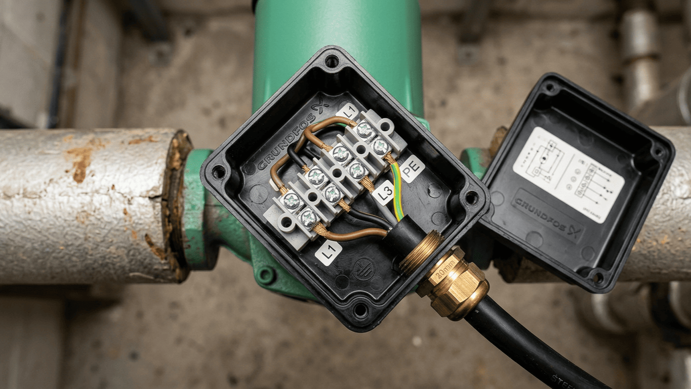
The terminal box sits directly on top of the motor housing, accessible via four screws on the cover plate. Inside, you will find a compact but well-organised space with clearly marked terminals for power supply, earth connections, and control wiring. Procuring your commercial pumps through Heating and Plumbing World ensures you receive genuine units with pristine, factory-sealed terminal boxes.
The main power connections accept either a three-phase 400V terminal setup or a single-phase supply depending on your exact model specification. Most commercial installations utilise the three-phase 400V terminal, but the single-phase 230V variant uses the identical box layout with different labelling. Don't assume anything. Always check the rating plate on the side of the pump before you start pulling cable.
The earth terminal is positioned separately from the live connections, marked with the standard earth symbol and typically painted green. Proper earthing on circulator pumps prevents dangerous voltage potentials on the casing, especially in wet plant room environments.
Cable Selection And Sizing Requirements
The cable you choose matters far more than most installers realise. Pumps fail prematurely simply because someone used undersized cable or the wrong insulation type for the environment.
For commercial installations, you'll need four-core armoured cable SWA in most settings. The sizing depends on the cable run length and circuit protection, but 2.5mm² typically handles the current draw up to 25 metres. Longer runs require strict voltage drop calculations, as the motor won't thank you for running on reduced voltage. When routing your four-core armoured cable SWA near fragile push fit plumbing fittings, ensure adequate clipping to prevent mechanical strain.
The cable insulation temperature rating must match or exceed the ambient temperature in your plant room. Standard PVC-insulated cable is rated to 70°C. Hot plant rooms or installations near boiler flues need heat-resistant variants rated to 90°C or higher.
Step-By-Step Terminal Box Access And Preparation
Start by isolating the power supply at the distribution board. Lock off the isolator and test for dead using a dedicated proving unit, not just a standard voltage indicator.
Remove the four screws securing the terminal box cover using a flat-head screwdriver. The screws often sit in rubber grommets that prevent water ingress. Place them safely in a magnetic tray, not on the floor where they will vanish. Inside the box, check the condition of the rubber seal on the underside of the cover. Cracked or compressed seals let moisture in, which inevitably ends badly. Replace damaged components immediately to maintain the correct water flow capacity and protect the internal electronics from corrosion.
The cable entry points on the box accept a standard 20mm cable gland seal. Most installations use one 20mm cable gland seal for power and a second for control wiring if needed. Unused entry points must have blanking plugs fitted securely.
Power Supply Connection Procedure
Feed your power cable through the gland, leaving enough slack inside the box for comfortable working. Tighten the gland body finger-tight, then add half a turn with a spanner. Overtightening crushes the cable, and undertightening allows dangerous movement.
Strip the outer sheath back to just inside the gland, exposing the individual cores. The armour should clamp firmly without sharp edges protruding into the box. Strip 10mm of insulation from each core using proper wire strippers, rather than a knife. Knife-stripped cores have dangerous nicks that create weak points. Twist the stranded conductors clockwise to tighten them perfectly.
Match your incoming supply phases to the appropriate three-phase 400V terminal markings. Phase rotation doesn't matter for the pump motor, as it will run in the correct direction regardless. However, keeping phase rotation consistent across all units makes future maintenance far easier, especially when cables are routed alongside bulky pipework insulation. Tighten terminal screws firmly using a proper screwdriver to exactly 1.2Nm of torque.
Control Wiring Integration
The control terminals allow external switching through volt-free contact switching. This means your building management system or plant room controller can start and stop the pump without handling mains voltage.
Control wiring typically uses 0.75mm² or 1.0mm² two-core cable, run entirely separately from the power supply to avoid interference. Think of control wiring like the nervous system of the building, while the power cables act as the heavy muscles. The nervous system requires absolute precision and isolation to send clear signals without electrical interference from the heavy lifting taking place right next to it.
Connect your control cable to the terminals marked for external control. Providing dedicated volt-free contact switching ensures seamless integration with a comprehensive heating system control panel. The control circuit operates at extremely low voltage and draws minimal current. Don't be tempted to share control cable cores with other circuits.
Testing And Commissioning Checks
Before you close up the terminal box and energise the pump, perform a thorough visual inspection. Look for any loose strands of conductor that might bridge terminals, check that all screws are tight, and verify that the 20mm cable gland seal is properly compressed.
Use a multimeter to test insulation resistance between live conductors and earth. You should see megohms, not kilohms. Low insulation resistance indicates damaged cable or contamination in the terminal box. Don't energise a pump with poor insulation readings.
Refit the terminal box cover with its seal properly seated in the groove. Tighten the four screws in a diagonal pattern to ensure even compression. At the distribution board, energise the circuit and check for normal operation. Much like commissioning a secondary water circulation pump, the Grundfos UPC 40-60 commercial pump should start smoothly without excessive noise or vibration.
Common Installation Mistakes And How To Avoid Them
The most frequent error engineers encounter involves incorrect cable gland sizing. Using a 25mm gland on a 20mm entry point creates a poor seal and allows severe moisture ingress.
On a recent hospital plant room upgrade, an apprentice stripped the primary cores with a blunt knife and nicked the copper. Three weeks later, the resulting hot spot melted the terminal block entirely, causing an emergency shutdown across the entire heating wing. Attention to basic termination details prevents these catastrophic failures.
Failing to bond the steel wire armour to earth is another major error. The armour provides an excellent earth path, but only if you connect it properly at both ends. A flying earth lead from the gland to the earth terminal takes seconds to fit and prevents potential shock hazards. Leaving the terminal box cover loose invites moisture problems. The five seconds it takes to check the seal properly saves hours of fault-finding later.
Maintenance Access And Future Modifications
Design your installation with future access firmly in mind. Position the pump so the terminal box cover can be removed without dismantling pipework or moving other heavy equipment. Installations where accessing the terminal box requires draining down the system showcase extremely poor planning.
Label your cables at both ends with clear, permanent marking. Labels fade and fall off, so use a label printer or write on heat-shrink sleeving for permanent identification. Keep a wiring diagram securely in the plant room. When someone needs to fault-find at three in the morning on a Saturday, that diagram becomes utterly invaluable. Include terminal designations and circuit breaker ratings clearly.
If you are adding external volt-free contact switching wiring to an existing installation, isolate the main power supply first. The control circuit might be low voltage, but the deadly power terminals sit millimetres away.
Conclusion
Wiring the terminal box properly the first time prevents callbacks, premature failures, and dangerous safety hazards. The process isn't complicated. You simply need to select appropriate four-core armoured cable SWA, make secure connections, and seal the box correctly.
Taking an extra ten minutes during installation to double-check connections, test insulation resistance, and verify proper sealing pays huge dividends throughout the pump's service life. Most failures trace back directly to poor installation practices rather than internal equipment faults. Keep the terminal box clean and dry, ensure all connections are tight, and if you need further technical guidance, contact our support team to ensure your next commercial installation is completely compliant and secure.