
Grundfos UPS3 15-50/65: Underfloor Heating Manifold Integration And Wiring
The Grundfos UPS3 15-50/65 delivers 4.5 metres of head pressure and moves 3.3 cubic metres per hour at maximum capacity. This performance makes it one of the most specified circulators for residential underfloor heating systems. While A-rated energy efficiency is a key selling point, a successful grundfos ups3 underfloor heating manifold integration relies on precision during the physical setup and wiring phases.
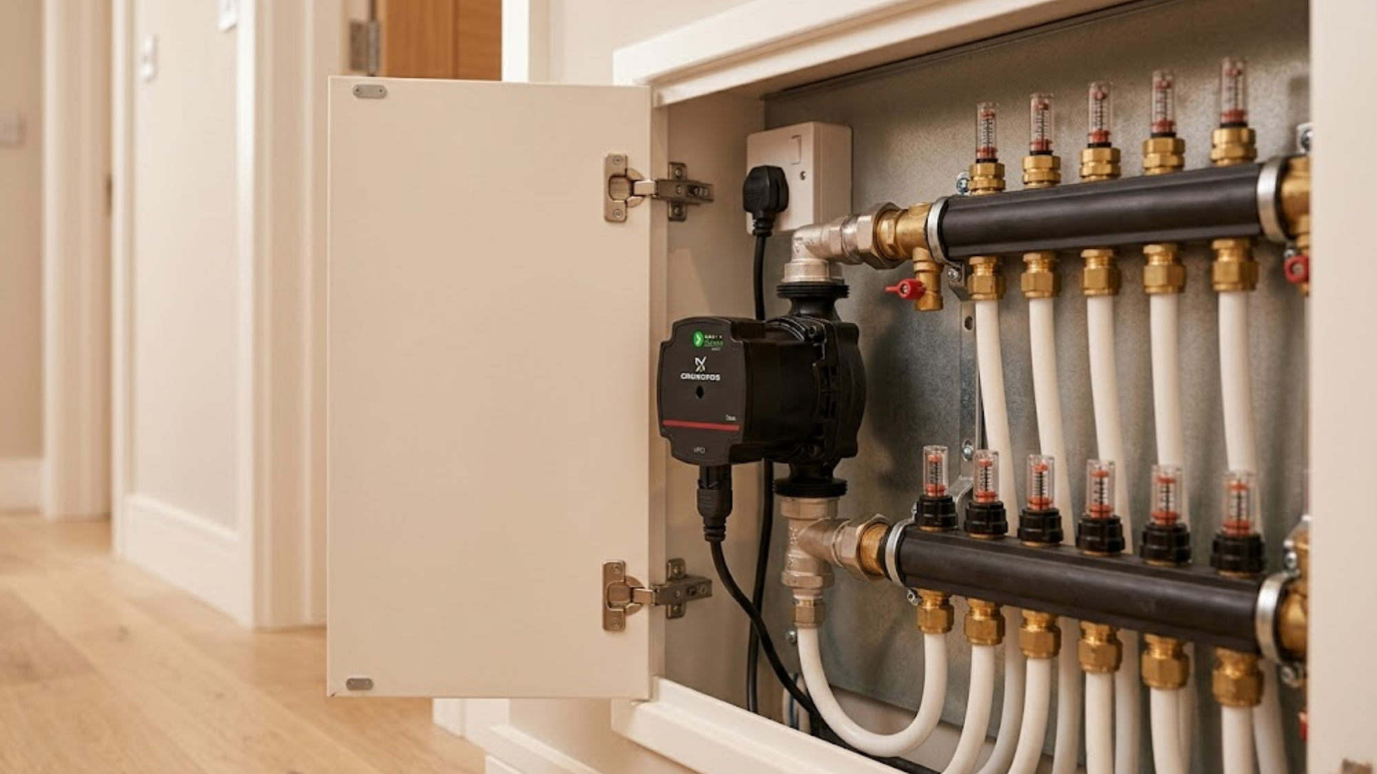
Physical Installation On The Manifold
Mount the unit with the motor housing horizontal and the shaft parallel to the floor. The pump body can rotate 360 degrees for flexible pipe alignment, but the motor must stay level to prevent premature bearing wear. Heating and Plumbing World supplies these units with the necessary fittings for immediate manifold attachment.
Executing a proper 1½" BSP union connection is vital. These unions connect directly to standard manifold ports without adapters. Tighten the union nuts to 40-45 Nm using a strap wrench on the pump body for counter-torque.
Think of the auto-adapt mode on this pump like a high-end audio system that automatically adjusts its volume based on the background noise in the room. Just as the stereo finds the perfect level so you can hear every note without it being deafening, the pump finds the exact pressure required to satisfy every circuit without wasting energy or creating noise.
Avoid the temptation to use excessive force during the 1½" BSP union connection, as over-tightening damages the O-rings and causes slow leaks that appear weeks after commissioning. Always install isolation valves on both sides of the pump to permit servicing without draining the radiator heating system or the floor circuits.
Understanding The Auto-Adapt Mode
The pump ships in auto-adapt mode, which adjusts speed based on system resistance. When zone valves close and flow decreases, the pump automatically reduces speed to maintain optimal differential pressure. This prevents noise and extends the life of actuators by eliminating pressure spikes. Selecting high-quality heating controls that communicate effectively with the pump is essential for system longevity.
Auto-adapt measures the load every 24 hours and creates a performance curve matching the specific installation. For the first three days, you will hear slight speed variations as the unit maps the system. This mode works best in systems with 4 to 12 zones and actuators that modulate gradually.
Constant Pressure Mode Configuration
Switch to constant pressure mode when you need predictable flow regardless of how many zones operate. Press the mode button once to change the LED from green to red. In this mode, the unit maintains the set differential pressure by varying speed.
This ensures a consistent heat output to open zones even when most of the system shuts off. Use the adjustment buttons to set the pressure between 0.2 and 0.45 bar, often required when integrating with a secondary expansion vessel.
Wiring For Standalone Operation
The unit requires a 230V AC single-phase power supply. It draws between 5 and 45 watts depending on the load, with a maximum current of 0.35A. Access the terminal block under the grey cover on the motor housing by rotating it counter-clockwise.
Professional installers use a 3-amp fused spur dedicated to the pump circuit. This protects the internal electronics and provides local isolation. If the pump sits more than 20 metres from the consumer unit, check your plumbing fittings and supplies for the correct 2.5mm² cable to prevent voltage drop. Mount the spur within sight of the manifold cabinet for easy emergency shutdown.
Integration With Wiring Centres
Connecting the pump to a wiring centre allows it to cycle based on zone calls for heat. Most wiring centres provide a switched 230V output, typically labelled as the wiring centre auxiliary output or pump terminal.
Run a 1.5mm² cable from the wiring centre auxiliary output to the pump's L terminal. This setup ensures the pump stops completely during long idle periods rather than running at minimum speed. Ensure your room thermostat is correctly paired with the wiring centre to trigger the wiring centre auxiliary output reliably.
Parallel Pump Control For Zoned Systems
Large installations sometimes use two pumps in parallel, each serving separate sections. You can wire both units to the same wiring centre auxiliary output so they start together. Two UPS3 units pull a combined 0.7A, well within the 3-amp capacity of standard controls.
Set both pumps to identical modes and pressure settings. Mismatched settings cause one pump to work harder, creating uneven wear. Check the LED indicators monthly to verify both units run at similar speeds under normal load.
Troubleshooting Common Wiring Issues
If the pump fails to start, verify 230V at the terminals using a multimeter. No voltage indicates a problem with the supply circuit or the wiring centre auxiliary output. If voltage is present but the LED remains dead, the internal electronics have likely failed.
A continuously red LED suggests a fault, often caused by air in the system creating dry-running. Bleed the pump by loosening the slotted screw in the centre of the motor housing. Excessive noise usually means incorrect mounting orientation or debris in the radiator valves. Increasing the system pressure to 1.5 bar can help dissolve trapped air and push it toward bleed points.
Balancing Flow After Installation
Commission the system with all zone valves fully open. Set the pump to constant pressure mode and begin the manifold flowmeter balancing process. Read the flow rates on each circuit using the built-in flowmeters; they should show values within 10% of the design specifications.
On a recent 150m² residential project, a technician over-tightened the union nuts using a large pipe wrench without providing counter-torque. The stress cracked the manifold port and distorted the pump O-ring, leading to a significant leak during the pressure test. It required a full manifold replacement and two extra days on site, a costly reminder that the 1½" BSP union connection requires a delicate hand.
If flows vary, adjust the balancing valves on each circuit. This manifold flowmeter balancing takes approximately 20 minutes and dramatically improves comfort. Once balanced, you can switch back to auto-adapt if desired.
Electrical Safety And Compliance
All wiring must comply with BS 7671 requirements. Because the pump operates in a wet environment, the installation of 30mA RCD electrical protection is non-negotiable.
Ensure the plastic pipe systems nearby are correctly supported to prevent mechanical stress on electrical connections. Maintain a 50mm minimum separation between the electrical terminals and any pipework. Label the isolation point clearly with the model number and installation date for future maintenance records.
Long-Term Performance Monitoring
The UPS3 displays real-time power consumption on the LED panel. Recording these values during commissioning provides a baseline reference. Check the display quarterly; power consumption should remain stable. Increasing power draw suggests system fouling or air accumulation creating extra resistance.
The pump should run whisper-quiet. Any new noise indicates bearing wear or debris. Catching these issues early during routine maintenance ensures the grundfos ups3 underfloor heating manifold integration delivers its full 15-year design life.
Conclusion
The UPS3 transforms underfloor heating efficiency when integrated correctly. Methodical manifold flowmeter balancing, secure mounting, and correct electrical wiring are the foundations of a reliable system. By choosing the right control strategy and ensuring 30mA RCD electrical protection is in place, you maximise comfort and energy savings. If you require assistance with manifold settings or wiring diagrams, speak to our team for technical guidance today.