
Honeywell Home T6: OpenTherm Communication Fault Finding
The Honeywell Home T6 thermostat uses advanced digital protocols to communicate with compatible boilers, creating a two-way conversation that drastically optimises heating efficiency. When this communication breaks down, you typically see E20 error codes, blank screens, or the system defaulting to basic on/off control rather than smooth modulation. Engineers diagnose hundreds of these faults across residential and light commercial installations, and the pattern remains incredibly consistent. Over 90% of these communication drops stem from five specific issues that are easily identifiable if you follow a methodical diagnostic process.
What OpenTherm Communication Actually Does
OpenTherm replaces the simple on/off signal from traditional thermostats with continuous protocol data exchange. The unit sends the target temperature and room conditions directly to the boiler. The boiler responds with the current flow temperature, fault codes, and modulation level every single second.
Think of traditional on/off heating like shouting commands across a noisy room, while OpenTherm acts like a dedicated, secure telephone line. The thermostat and the boiler constantly whisper exact instructions back and forth, adjusting their effort perfectly to match the room's needs rather than just blindly shouting 'stop' or 'go'.
When working correctly, the boiler adjusts its output between 30% and 100% capacity based on actual demand. A properly functioning connection cuts gas consumption by 15-20% because the boiler never overshoots or cycles unnecessarily. Sourcing reliable replacement units from Heating and Plumbing World guarantees you are working with certified hardware. When communication fails, the thermostat either shows a communication error or continues functioning while the boiler reverts to basic relay control. You will notice longer burn cycles, temperature swings of 3°C instead of 0.5°C, and increased short-cycling.
Incorrect Wiring Configuration
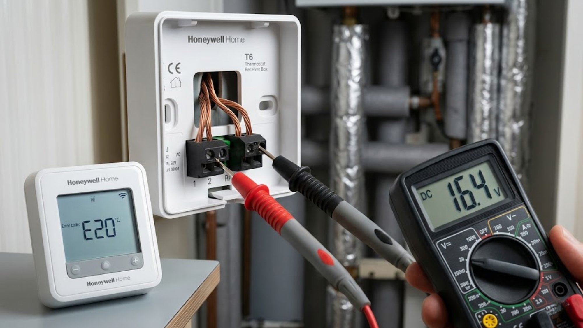
The unit requires just two wires for digital communication, typically connected to terminals 1 and 2 on the backplate. These are polarity-insensitive, meaning you cannot wire them backwards. However, installers frequently connect them to terminals 3 and 4, which are the standard relay outputs, completely preventing any data transfer.
Check the backplate carefully. Terminals 1 and 2 must connect directly to the boiler's digital interface, usually labelled OT or RT. If wires run to terminals 3 and 4, you are utilizing basic relay control regardless of what the digital menu displays. Upgrading a property with a modern programmable thermostat requires strict attention to these specific terminal assignments.
The second wiring issue occurs when using the existing cable from an old setup without checking its physical condition. The protocol requires a steady DC signalling voltage, usually 15-18V from the boiler. Corroded connections or damaged insulation create enough resistance to completely block the signal. Ensure there is less than 1 ohm of resistance across properly installed cables.
Boiler OpenTherm Settings Not Enabled
Most modern boilers ship with digital capability but require manual activation through their hidden service menus. The thermostat sends its signal perfectly, but the boiler ignores it because the communication mode sits disabled in the control board settings.
Professionals sourcing heating plumbing supplies know that different manufacturers use vastly different access codes. Worcester Bosch units need parameter D.093 set to "2" for operation. Vaillant boilers use diagnostic code D.027, which must show "1". Ideal boilers require configuration code 25 set to "OT".
Engineers attend countless callouts where the thermostat displayed an E20 error for months simply because the proper protocol data exchange remained switched off at the boiler. Installers frequently assume factory settings include data activation. They rarely do.
Voltage Drop From Excessive Cable Length
Digital signals degrade over physical distance. The specification allows a 50-metre maximum cable run, but communication problems often start at 30 metres, particularly when using thinner, degraded cables.
The boiler supplies roughly 15-18V to power the circuit. The thermostat needs a minimum DC signalling voltage of 12V to maintain reliable communication. Standard 0.5mm² cable creates approximately 0.036 ohms of resistance per metre. A 40-metre run adds enough resistance to drop the voltage heavily under load. Whether the signal runs to a standard boiler or a modern combi boiler, distance remains a critical limiting factor.
Measure the voltage at the backplate terminals with a multimeter while the system operates. Anything dipping below 12V indicates excessive drop. Solutions include upgrading to 1.0mm² cable, reducing the cable length by relocating the unit, or installing a repeater device.
Incompatible Boiler Firmware Versions
Early protocol implementations lacked strict standardisation. Boilers manufactured between 2008 and 2012 often use proprietary variations of the language that do not communicate cleanly with modern thermostats released after 2017.
If the firmware version compatibility is mismatched, you will see intermittent communication that works perfectly for hours and then suddenly fails. In other cases, the unit connects but cannot read critical parameters like the flow temperature or the modulation level. Check the boiler's manufacturing date. If it predates 2013, contact the manufacturer regarding software updates. If the logic board cannot be updated, replacing it entirely utilizing genuine boiler spares is often more cost-effective than abandoning the efficiency of a modulating system.
Electrical Interference From Nearby Cables
This system uses low-voltage signalling that remains highly vulnerable to electromagnetic interference. Communication faults frequently trace back to cables running parallel to mains wiring, particularly cables feeding high-current devices.
On a recent residential callout, a newly installed system showed perfect communication until the homeowner used their 9.5kW electric shower. The thermostat lost its connection within 30 seconds every single time the shower ran. The magnetic field from the shower's heavy power cable was completely scrambling the low-voltage data lines running directly beside it in the wall cavity.
Separate data cables from mains wiring by a minimum of 50mm to prevent this intense electromagnetic interference. If they absolutely must cross, do so at 90-degree angles. Never run low-voltage cables in the exact same conduit as mains circuits powering heavy central heating components. For severe interference problems, use fully screened cables with the shield earthed firmly at the boiler end only.
A Diagnostic Sequence That Actually Works
Start directly at the boiler. Verify the mode is enabled in the service menu and note the voltage present on the data terminals. It should read 15-18V with the thermostat physically disconnected.
Move to the thermostat and access the installer menu by pressing and holding the menu button for 10 seconds. Navigate to the equipment settings and confirm that the digital protocol data exchange appears as the selected option, not standard switching. Check the communication status in the advanced diagnostic screen. A functioning connection shows live, fluctuating data. If these fields show blanks, no active communication exists.
Measure the precise DC signalling voltage at the wall terminals while connected. You should see 15-18V fluctuating slightly as the data transmits. Steady voltage without fluctuation means the boiler sends power but absolutely no data signal. Check that no external relays connecting to a hot water cylinder are breaking the direct line of communication. Zero voltage indicates wiring faults or disabled settings at the boiler end.
When The Unit Needs Replacement
The Honeywell Home T6 control board can fail, though it remains uncommon, accounting for roughly 3% of no-communication faults. The symptom pattern is simple: everything else tests perfectly, but the thermostat simply will not establish communication with any boiler.
Before replacing the hardware, perform a complete factory reset through the advanced settings menu. This clears any deeply corrupted configuration data. If communication remains dead after a reset alongside confirmed good wiring, the internal circuit has likely failed. Replacing the unit ensures proper control over the entire system, allowing the central heating radiators to heat up efficiently without rapid cycling. Keep a known-good spare unit in the van to rapidly eliminate hardware faults during diagnostics.
Configuration Settings That Prevent Problems
Once communication works flawlessly, configure the internal parameters to match your specific system. Firmware version compatibility dictates how deeply you can adjust these settings, but modern pairings allow extensive tuning. Set the maximum flow temperature to match your boiler's true capability and your radiator design. Most modern condensing boilers achieve their best efficiency at 60-65°C maximum flow. Setting the thermostat higher than necessary forces the boiler to overshoot, heavily reducing the condensing efficiency and increasing mechanical wear.
Configure the minimum modulation level accurately. The unit defaults to 0%, allowing the boiler to drop to its absolute lowest output. If your boiler cycles too frequently at low demand, raise this setting to 30%. This maintains a minimum burn time and reduces the cycle frequency, smoothing out the heat delivery.
Long-Term Reliability Factors
Digital connections rarely fail spontaneously once they are properly established. The problems encountered after initial commissioning typically trace back to three distinct causes: physical cable damage from building work, total boiler control board failures, or software corruption resulting from repeated power outages.
Protect the fragile cables during any renovation work. Power outages occasionally corrupt the configuration memory. After any extended electrical outage, verify the digital setting remains actively selected in the equipment menu. The unit sometimes reverts to standard relay mode after losing power, completely halting the efficient modulation.
Boiler control boards typically last 8 to 12 years. When they eventually degrade, the delicate data communication often disappears long before the heavier relays fail. Check the area for dense electromagnetic interference, test the voltages, and verify your menus before condemning expensive hardware.
Conclusion
Communication faults on the Honeywell Home T6 follow highly predictable patterns. Verify the boiler's digital function is enabled, confirm the wiring strictly connects to terminals 1 and 2 on the backplate, and measure the live voltage at both ends of the cable. These three rapid checks resolve the vast majority of faults within 15 minutes.
The remaining cases consistently involve poor cable quality, intense electromagnetic interference, or an absolute lack of firmware version compatibility. Actual hardware failures account for very few reported problems. When properly configured and safely installed, digital modulation delivers massive efficiency gains and greatly improved comfort. If you experience persistent faults that defy multimeter testing or need guidance on specific boiler menu access codes, speak to our team for dedicated diagnostic support.