
Honeywell Sundial S Plan: Motorised Valve Wiring And Microswitch Diagnostics
The Honeywell Sundial S Plan system controls heating and hot water independently through motorised valves. When these valves fail, the entire system breaks down. Roughly 40 faulty motorised valves are diagnosed every month in a typical busy service schedule, and 70% of these failures trace back to microswitch problems or incorrect motorised valve wiring.
The motorised valve sits at the heart of the S Plan configuration. When your programmer calls for heating, it sends a 240V signal to the valve motor. The motor rotates over 60-90 seconds, opening the valve to allow hot water flow. Once fully open, an internal microswitch closes, completing the circuit to fire the boiler. This sequencing prevents the boiler from firing when valves are closed, protecting the system from severe pressure damage.
How The Motorised Valve Motor And Microswitch Work Together
Professionals relying on Heating and Plumbing World for components know the valve head contains two critical parts: the synchronous motor and the microswitch assembly. The motor receives power through the grey wire for the common connection, the brown wire to open, and the orange wire to close. When 240V hits the brown wire, the motor rotates clockwise, opening the valve. When power switches to the orange wire, it rotates counter-clockwise, closing the valve. Correct motorised valve wiring ensures these directional signals arrive at the precise moment they are needed.
Think of the microswitch like a runner passing the baton in a relay race. The valve motor completes the initial leg of the race by physically opening the valve, but the boiler cannot start its leg until the microswitch physically clicks and successfully passes the electrical 240V signal forward.
This microswitch is a spring-loaded contact that physically clicks when the valve reaches full travel. In the open position, it connects the white and blue wires, sending 240V to the boiler's pump and burner circuits. This mechanical action creates an audible click. If you don't hear it when the valve should be open, microswitch diagnostics are required. The spring tension weakens over time, preventing reliable contact closure after approximately 50,000 cycles.
Standard S Plan Wiring Configuration
The Honeywell Sundial S Plan uses a minimum of two motorised valves: one for heating zones and one for hot water. Each valve connects to the system through a specific wiring centre terminal arrangement.
Terminal 1 takes the grey common wire. Terminal 2 takes the brown open wire. Terminal 3 takes the orange close wire. Terminal 4 takes the blue boiler call wire. Terminal 5 takes the white microswitch output wire. The programmer sends switching signals through this wiring centre to execute precise heating valve control across the entire property.
When heating is demanded, 240V appears at the heating call terminal. This routes through to the valve's brown wire, powering the motor to open. Once the microswitch closes, the blue wire receives power, which connects to the boiler's terminal block.
The earth wire from each motorised valve must terminate properly at the earth bar. A floating earth in your motorised valve wiring prevents the motor's thermal protection from functioning correctly, leading to total motor burnout when the valve jams. The hot water valve follows identical wiring principles but connects to separate programmer terminals, allowing completely independent control.
Diagnosing Microswitch Failures
When performing microswitch diagnostics, symptoms appear in predictable patterns. The boiler won't fire even though the valve motor operates normally. You will hear the motor complete its travel, but the system remains cold.
Always start the testing procedure by removing the valve head. Unscrew the locking nut at the base to expose the valve body and its manual lever. Set the manual lever to the open position to mechanically open the valve, bypassing the motor entirely. If the system fires and runs normally with the manual lever open, the valve body is highly functional. The problem sits in the head assembly. Either the motor isn't completing full travel, or the microswitch isn't closing despite full travel.
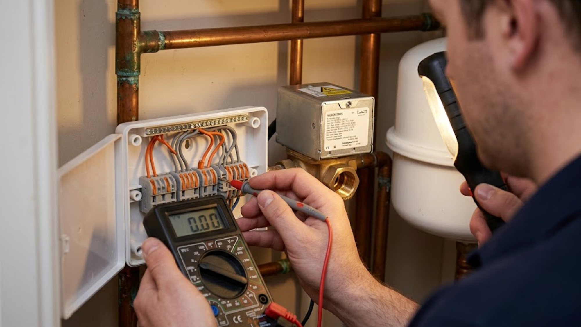
Reconnect the valve head and power the system. Place your hand on the valve body while the motor runs. You should feel slight vibration for 60-90 seconds before it stops. At the exact moment it stops, you should hear a distinct click. No click means complete microswitch failure. For electrical confirmation, test continuity between the white and blue wires with the valve powered open. You should read 0 ohms. An infinite resistance reading means the microswitch contacts aren't closing. It is much more cost-effective to utilise standard boiler spares to replace just the head assembly rather than replacing the expensive bronze casting of the complete valve body.
Motor Winding Failures And Thermal Cutout Testing
The synchronous motor contains thermal protection via a bimetallic disc that breaks the circuit when the motor overheats. This typically triggers when the valve jams mechanically, forcing the motor to stall under a heavy load.
When testing a suspected motor failure, proper thermal cutout testing is essential. Measure the resistance across the motor windings with the valve head disconnected from the wiring centre. Using a multimeter set to ohms, the grey to brown wires should read 800-1200 ohms. The grey to orange wires should read 800-1200 ohms. The brown to orange wires should read 1600-2400 ohms for the combined windings.
If any reading shows infinite resistance, the thermal cutout has opened or the winding has failed. Effective thermal cutout testing involves allowing the unit to cool for 30 minutes, as the thermal cutout sometimes resets. Scale buildup inside the valve body increases mechanical resistance, drastically increasing motor current draw. A properly maintained gas boiler expansion vessel keeps system pressure stable to help mitigate extreme load conditions that push debris into these tight mechanisms.
Wiring Centre Terminal Diagnostics
The Sundial wiring centre orchestrates all heating system control logic. When systems fail intermittently or behave unpredictably, the fault often hides in the wiring centre rather than the valves themselves.
On a recent commercial refit, an apprentice replaced three entire valve bodies because the boiler wouldn't fire. A simple multimeter check later revealed the actual culprit was a heavily corroded neutral bar in the wiring centre dropping the voltage to 228V. It was an expensive lesson in following correct diagnostic sequences instead of just swapping parts.
For the terminal voltage testing procedure, measure the voltage at each wiring centre terminal with the system live while calling for heat at the programmer. Terminal 1 for neutral should read 0V to earth. Terminal 2 for live supply should read 240V to neutral. Terminal 3 for heating call should read 240V when heating is demanded. Terminal 5 for the boiler run should read 240V only when a valve microswitch successfully closes.
If Terminal 3 shows 240V but the heating valve doesn't activate, check the connection from Terminal 3 to the valve's brown wire. If Terminal 5 never shows voltage despite valves opening correctly, trace the white wire from each valve. Clean all neutral connections annually by removing each wire, wire-brushing the wiring centre terminal, and reconnecting it with proper torque to prevent heavy voltage drops.
Advanced Microswitch Adjustment
Some motorised valves allow microswitch timing adjustment, which changes exactly when the switch activates relative to the valve position. This adjustment sits inside the head assembly as a small cam or eccentric screw.
Advanced microswitch diagnostics will reveal if the valve reaches full open but the microswitch clicks before reaching that full travel path. This creates a situation where the boiler fires while the valve is still 80-90% open. Flow restriction causes pump over-run and rapid cycling throughout the entire radiator heating system.
Adjust in small increments of 5 degrees of cam rotation or a 1/8 turn of the eccentric screw. Power the valve open and verify the click occurs exactly at full travel. Over-adjustment causes the opposite problem, where the valve reaches full open but the switch doesn't click for another 3 seconds, delaying boiler startup time.
Parallel Versus Series Valve Wiring
The standard Honeywell Sundial S Plan configuration uses parallel valve wiring. Both valves connect independently to the wiring centre, and either valve can call the boiler. This configuration provides maximum flexibility but requires extremely careful motorised valve wiring.
Some installers wire valves in series when adding zones to existing systems. Series wiring connects the microswitch output of valve 1 to the input of valve 2. This approach to motorised valve wiring works functionally but creates massive diagnostic headaches. When the boiler doesn't fire, you can't isolate which valve's microswitch has failed without physical testing at each unit. Convert series-wired systems to a parallel configuration to reduce future diagnostic time dramatically.
Valve Replacement Without Draining The System
When a motorised valve fails completely, replacement doesn't require draining the entire heating system. Close the isolation valves on both sides of the failed unit. With both isolators closed, remove the valve head and unscrew the compression fittings connecting the valve body to the pipework. Have a container ready, as a small amount of water will drain from the valve body.
Install the new valve body, reconnect the compression fittings, and fit the new head assembly. Open one isolation valve slightly and vent air from the system at the nearest radiator. Ensure all system air is bled to prevent cavitation inside your heating pumps. Once water flows smoothly, open both isolators fully. Always replace the olive compression ring when reconnecting fittings to prevent callbacks for leaks.
Preventive Maintenance For Long Valve Life
Motorised valves last longest when they operate regularly and the system water remains perfectly clean. Exercise your valves monthly during summer by powering each valve through a complete open-close cycle. This prevents the motor gearbox from seizing and keeps the microswitch contacts from corroding.
Maintain correct inhibitor concentration by testing the system water annually. Check system pressure weekly. Low pressure causes pump cavitation, which sends debris through the system and scores the valve's internal seat, preventing complete closure.
Conclusion
Motorised valve problems stem from three primary causes: microswitch failure after normal wear, motor winding failure from thermal overload, or wiring issues at the connections. Systematic diagnosis isolates these causes rapidly when you understand the electrical relationships between the components. The microswitch remains the most common failure point.
Wiring centre problems create intermittent failures where valves operate but the boiler doesn't respond correctly. Voltage testing at each terminal while calling for heat reveals broken connections immediately. Most failures require only head assembly replacement, saving significant cost while restoring full system function. If you need assistance diagnosing a complex S Plan configuration, reach out to our experts for dedicated support and component matching.