
Pressure Relief Valves: Safety Device Selection
Every heating system operates under pressure. When that pressure exceeds safe limits, something has to give. Pressure relief valves (PRVs) exist to make sure what gives isn't your boiler, your pipework, or worse, the safety of building occupants.
The aftermath of systems without proper pressure relief includes cracked heat exchangers, burst cylinders, and catastrophic failures that shut down entire facilities. The right valve, correctly sized and installed, prevents these scenarios. The wrong one becomes a liability.
What Pressure Relief Valves Actually Do
A pressure relief valve opens automatically when system pressure exceeds a predetermined setpoint. It vents fluid, water, steam, or air until pressure drops back to safe levels, then closes again.
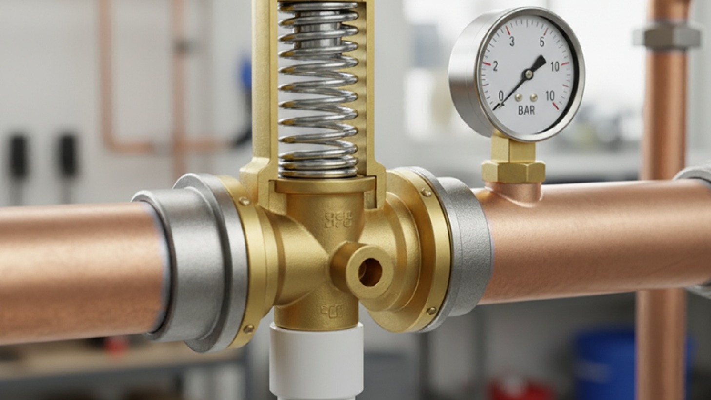
The mechanism is purely mechanical. No electronics, no external power. A spring holds the valve disc against the seat. When the pressure force overcomes the spring force, the disc lifts and fluid escapes. This simplicity makes PRVs reliable in emergencies when complex systems might fail.
Three Critical Specifications
These parameters define every PRV:
Set pressure: The pressure at which the valve begins to open (typically 90% of maximum allowable working pressure)
Discharge capacity: The volume of fluid the valve can release at a given pressure
Overpressure: How far above set pressure the valve must go to achieve full discharge capacity (usually 10% for liquids, 3% for compressible fluids)
A valve rated at 3 bar set pressure with 10% overpressure opens at 3 bar and reaches full flow at 3.3 bar. If your system's maximum allowable working pressure is 3.5 bar, this valve provides adequate protection. If it's 3.2 bar, you've specified incorrectly and left the system vulnerable.
Types of Pressure Relief Valves for Heating Systems
Spring-Loaded Safety Valves
Spring-loaded safety valves dominate heating applications. A calibrated spring provides the closing force. These valves work in any orientation and respond quickly to pressure changes. They're installed on unvented hot water cylinders, sealed heating systems, and anywhere rapid pressure rise poses a risk.
The spring determines the set pressure. Adjustable models let you fine-tune the setpoint, but fixed-spring valves are typically recommended for safety-critical applications. Fixed-spring valves eliminate the risk of unauthorised adjustment that could compromise system protection.
Temperature and Pressure Relief Valves (TPRV)
Temperature and pressure relief valves combine pressure relief with thermal protection. They open if either pressure or temperature exceeds safe limits. The thermal element, typically a wax-filled probe, extends into the fluid. When the temperature reaches the setpoint (usually 90-95°C for domestic systems), the wax expands and mechanically opens the valve.
TPRVs are mandatory on unvented hot water cylinders in most jurisdictions. The thermal function provides backup protection if the thermostat fails and the cylinder overheats, even if pressure remains within normal range. Quality cylinders from manufacturers like Gledhill and Kingspan come with appropriately rated TPRVs as standard.
Pilot-Operated Relief Valves
Pilot-operated relief valves use the system pressure itself to keep the main valve closed. A small pilot valve controls a larger main valve. When pressure exceeds the setpoint, the pilot opens, reducing pressure on top of the main valve disc, which then opens.
These valves offer tighter shutoff than spring-loaded types and handle higher capacities in smaller bodies. They're specified for large commercial systems where space is limited or where precise pressure control matters. They cost more and require cleaner fluids than spring-loaded valves, making them excessive for most residential applications.
Sizing Pressure Relief Valves Correctly
A valve too small for the heat input cannot discharge enough fluid to prevent dangerous pressure buildup. A valve too large costs more and may chatter, repeatedly opening and closing, which damages the seat and causes premature failure.
The sizing calculation starts with heat input. For boilers and water heaters, you need the maximum heat input rate in kilowatts. For systems with multiple heat sources, sum them all.
British Standard BS 6759 provides the formula for liquid relief:
Required discharge capacity (kg/h) = Heat input (kW) × 3.6 × Safety factor / Specific heat
For water systems, this simplifies to approximately 1.5 kg/h per kW of heat input with a 1.4 safety factor built in.
A 24 kW combi boiler requires a valve capable of discharging 36 kg/h. A 150 kW commercial boiler needs 225 kg/h capacity.
Valve manufacturers publish capacity tables showing discharge rates at various overpressures. You match your required capacity to the valve size that meets or exceeds it at 10% overpressure for the relevant set pressure.
Steam System Considerations
For steam systems, the calculation differs. Steam is compressible, and the valve must handle both the mass flow and the energy content. Different formulas are used based on whether the valve operates in critical flow (high pressure drop) or subcritical flow conditions.
Most heating system PRVs operate in critical flow, where discharge capacity is independent of downstream pressure. The valve effectively becomes choked, and downstream conditions don't affect performance.
Common Sizing Mistakes
- Using vessel volume instead of heat input (volume doesn't determine how fast pressure rises)
- Forgetting to account for all heat sources in multi-boiler systems
- Selecting based on connection size rather than discharge capacity
- Undersizing to save money (the valve costs £50; the damage from failure costs thousands)
When specifying pressure relief valves for complex systems, calculation rather than guesswork is essential. The 30 minutes spent on proper pressure valve selection prevents years of problems.
Set Pressure Selection
The set pressure must be low enough to protect the system but high enough to avoid nuisance opening during normal operation.
The standard approach: Set pressure = 90% of the maximum allowable working pressure (MAWP) of the weakest component.
A system with six bar-rated components throughout should have PRVs set at 5.4 bar. This provides a safety margin to ensure the valve opens before any component faces pressure beyond its rating.
For unvented cylinders, building regulations typically require 6 bar PRVs on systems operating at 3-4 bar. This seems conservative until you consider thermal expansion. As water heats from cold to 60°C in a sealed system, pressure can rise 2-3 bar. The higher set pressure prevents the valve from weeping during normal heating cycles and during protection against runaway scenarios.
Multiple PRV Configuration
Multiple PRVs in one system should have identical set pressures. Staggered setpoints sound logical: a 4-bar valve for normal protection and a 5-bar backup, but this approach fails in practice. If the first valve doesn't handle the full discharge capacity, pressure continues rising until the second valve opens. Now, both valves operate simultaneously, neither seats properly, and both leak after the event.
Instead, multiple valves of the same rating sized together provide the required total capacity. If one fails closed, the others handle the full load at slightly higher overpressure.
Discharge Pipe Requirements
A PRV that can't discharge properly can't protect the system. The discharge pipe, the pipework from the valve outlet to its termination point, matters as much as the valve itself.
Discharge Pipes Must:
- Terminate in a visible location where discharge is obvious (not inside walls or under floors)
- Run continuously downward with no pockets where water can collect and freeze
- Have no valves or restrictions between the PRV and the termination point
- Be sized to handle full valve discharge without creating excessive backpressure
British Standard BS 6700 specifies minimum discharge pipe sizes. For valves up to ½" BSP, use 15mm copper minimum. For ¾" valves, use 22mm minimum. These sizes assume relatively short runs with minimal elbows. Professional-grade copper fittings ensure reliable, leak-free connections in discharge pipework.
Backpressure Considerations
Backpressure kills capacity. Every elbow, every metre of pipe, every size reduction creates a pressure drop. If backpressure exceeds 10% of the set pressure, the valve cannot achieve its rated capacity. A 3-bar valve with 0.4 bar backpressure functions as if it's undersized.
Backpressure calculation uses standard hydraulic formulas or the manufacturer's tables, for most residential installations with short runs (under 3 metres) and minimal fittings, standard pipe sizing works. For longer runs or commercial systems, calculation becomes necessary.
Safe Discharge Termination
Discharge termination must be safe. The Building Regulations Approved Document G3 requires discharge from unvented cylinder PRVs to terminate:
- At a tun dish located in the same space as the cylinder, with a visible air gap
- Or at a metal pipe terminating externally in a visible location at least 300mm from any opening into the building
The goal is twofold: make discharge obvious so someone investigates, and prevent scalding water from injuring people. Valves discharging into floor voids for months cause rot and mould because nobody knew they were operating.
Installation Best Practices
Mount PRVs vertically with the inlet at the bottom and outlet at the top. This orientation keeps the valve body full of fluid and ensures debris doesn't settle on the seat. Most manufacturers allow horizontal installation in specific applications, but vertical remains the default.
Install valves directly on the vessel or system they protect. Don't put isolation valves between the PRV and the protected equipment. If you need isolation for maintenance, use a three-valve manifold that allows testing and removal without leaving the system unprotected.
Connection Point Placement
The connection point matters. On cylinders, mount the PRV at the top where pressure is highest and steam can form if the system overheats. On sealed heating systems, install at the highest pressure point, typically the boiler flow connection or the top of the system.
Support discharge pipes independently. Don't let the pipe weight hang on the valve body. Stress from unsupported pipework can distort the valve body and cause leaking. Use pipe clips every 500mm on vertical runs, every 300mm on horizontal runs.
Clean the system thoroughly before commissioning. Debris from installation, swarf, flux, hemp, and PTFE can lodge in the valve seat and prevent proper closure. Countless "faulty" valves are actually perfectly good valves with a particle stuck in the seat.
Testing and Maintenance
PRVs should lift when you test them. If they don't, they might not work in an emergency.
Manual testing: Most valves have a test lever that mechanically lifts the disc off the seat. Operate this lever annually to verify the valve opens and closes. You should see discharge, then a clean shut-off when you release the lever.
A valve that doesn't discharge when tested may be blocked or corroded. A valve that discharges but doesn't stop when released has a damaged seat or debris preventing closure. Both conditions require valve replacement.
Automatic testing isn't possible without specialised equipment. You can't safely overpressurise a system to verify the PRV opens at the correct setpoint. That's why pressure valve selection and installation matter; you need to trust the valve works because you can't routinely prove it.
Common Failure Modes
Weeping: Slow discharge even when pressure is below setpoint, usually from debris on the seat or corrosion
Chattering: Rapid opening and closing, often from undersizing or excessive backpressure
Failure to open: Corrosion, debris, or mechanical damage preventing the disc from lifting
Failure to close: Seat damage, debris, or spring failure preventing proper shutoff
Replace any valve that shows these symptoms. PRVs are not repairable in the field. The cost of a new valve (£20-100 for typical heating applications) is negligible compared to the risk of a failed safety device.
Regulatory Requirements
In the UK, the Building Regulations Approved Document G3 mandates specific safety devices for unvented hot water systems. Every unvented cylinder must have:
- At least two temperature control devices (thermostat and high-limit cutout)
- A temperature relief valve or a combined temperature and pressure relief valve
- An expansion vessel or other method to accommodate thermal expansion
- A pressure relief valve, if the expansion device could fail
These requirements are prescriptive because unvented cylinders pose a significant risk if controls fail. Water heated above 100°C in a sealed vessel can flash to steam if pressure is suddenly released, causing explosive vessel failure. Quality expansion vessels from Altecnic provide reliable thermal expansion accommodation when properly sized.
Commercial and Industrial Requirements
The Pressure Equipment Directive and UK Pressure Systems Safety Regulations 2000 apply to commercial and industrial systems. Systems above certain pressure-volume thresholds require:
- Written scheme of examination by a competent person
- Regular inspection and testing
- Record keeping of all examinations
- Immediate reporting of certain failures
These regulations ensure systematic attention to pressure safety rather than hoping someone remembers to check the valves.
Critical Safety Protection
Pressure relief valves represent the last line of defence against catastrophic pressure failure. They're simple devices with a critical job: open when needed, close when pressure normalises, and sit ready for decades between operations.
Selection starts with understanding your heat input and system pressure, then matching those requirements to a valve with adequate capacity at the appropriate set pressure. Installation demands attention to orientation, discharge piping, and accessibility for testing. Maintenance is minimal but essential, with annual testing to verify operation and immediate replacement if the valve shows any sign of malfunction.
The £50 valve protects thousands of pounds of equipment and, more importantly, the people who live and work around that equipment. Specify it correctly, install it properly, and test it annually. The valve you never think about is doing its job. The valve that makes you think about it needs replacement.
For comprehensive guidance on pressure relief valves suitable for domestic and commercial heating systems, Heating and Plumbing World stocks safety devices from specialist manufacturers, including Honeywell and other leading brands. Professional-grade pressure relief valves ensure reliable protection for sealed systems, unvented cylinders, and commercial installations. For technical advice on pressure valve selection specific to your system requirements, experienced heating engineers can provide support on correct sizing, installation, and compliance with building regulations.