
Testing Boiler PCBs: Multimeter Diagnostics Before Replacement
A faulty printed circuit board can shut down an entire heating system. This often leaves homeowners in the cold and engineers scrambling for fast solutions. However, you should remember that not every boiler lockout means you need a £300 replacement. Frequently, the problem is something much simpler than a failed control unit.
I have seen too many engineers swap out boards without performing proper diagnostics first. Consequently, the same fault often reappears because the root cause was never addressed. A blown board is often a symptom, rather than the actual disease. This is why testing boiler pcbs with a multimeter is worth its weight in gold.
Testing a board properly takes about fifteen minutes and can save your customer hundreds of pounds. It is not complicated, but it does require a methodical approach. Understanding exactly what you are measuring is the first step toward a successful repair.
Understanding The Logic Of Your Diagnostics
A boiler PCB is essentially the "brain" of the heating system. Much like a biological brain, it receives inputs from sensors and processes that information. It then sends specific electrical instructions to components like the gas valve, pump, and fan. When this brain fails, the entire system grinds to a halt.
Most failures fall into three main categories: power supply issues, component burnout, or relay failures. Your multimeter can identify which of these you are dealing with before you commit to a replacement. You can find essential trade heating supplies to help with your repairs once you've found the fault.
The key is working systematically through the board. Random voltage checks will not tell you very much about the health of the system. You need to understand the circuit path and test at specific points where failures commonly occur. Using multimeter diagnostics allows you to trace these paths accurately.
Safety First: Electrical Isolation
Safety should go without saying, but I have watched young engineers cause dangerous arcs by testing live circuits. You must always isolate the boiler electrically before removing the protective cover. Switch off the power at the isolation switch and verify there is no voltage present.
Check between live and neutral, then live and earth, to confirm the system is dead. Only when you have confirmed zero voltage should you proceed with the repair. Even with the power off, you should discharge any capacitors on the board. Some boards hold a significant charge for several minutes after you have cut the power.
Testing The Power Supply Section
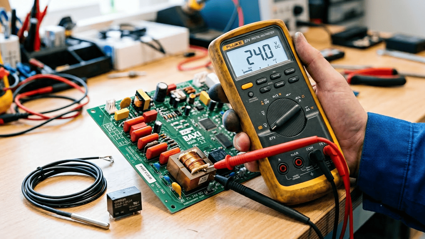
Start with the basics to see if the board is actually receiving power. Set your multimeter to DC voltage and check the main power input to the unit. Most boiler boards run on 12V or 24V DC, which is stepped down from the mains supply. This part of the pcb power supply is the foundation of the entire system.
Locate the transformer connections on the board to begin your pcb power supply checks. With the power restored carefully, measure the voltage across the transformer output. You should see a reading within 10% of the rated voltage. If the reading is significantly low or absent, the transformer itself has likely failed.
Next, you should check the rectifier and the smoothing capacitor. The transformer provides AC voltage, which the rectifier converts to DC. Measure the voltage after the rectifier to ensure it is stable. If you find excessive voltage ripple, the pcb power supply will not be able to operate the logic circuits correctly.
Component-Level Diagnostics
Once you have confirmed a clean power supply, you should move to the individual components. Relays are the most common failure point on any heating control board. They click away thousands of times over a boiler's life and eventually wear out. Use relay failure testing to find these faults early.
Test each relay with the power off by setting your multimeter to resistance. Measure across the relay coil terminals to look for an open circuit. If you see infinite resistance, the coil is broken. Furthermore, you should perform relay failure testing on the normally-open contacts to check for welded parts.
Listen for the relay to click when the boiler calls for heat. If you hear no click, the relay coil might be receiving voltage, but the internal mechanism has failed. In some cases, a failed relay might prevent a Bentone burner motor from starting up during the ignition sequence.
Testing Input And Output Circuits
A board can be perfectly healthy but appear faulty if it is not receiving signals from sensors. You should perform a thermistor resistance check to rule this out. These temperature sensors change resistance based on the heat of the water. Typically, they show around 10k to 15k ohms at room temperature.
Disconnect the sensor and perform your thermistor resistance check. Compare the reading to the manufacturer's chart. Furthermore, if the sensor is healthy, measure the reference voltage at the board terminals. This proves the board is providing the necessary power to the sensor circuit.
If the sensors are fine, you should check the output circuits for components like an Ecoflam gas burner. Measure the voltage at the output terminals when the boiler calls for heat. If the voltage is present but the component does not run, then the part itself is faulty.
Tracking Down Short Circuits
A short circuit somewhere in the system can blow board components or trip internal protection. This is where your multimeter's continuity function becomes invaluable. Disconnect all outputs from the board before you begin short circuit tracking.
Check each component individually by measuring its resistance to earth. A pump or fan motor should show very high resistance to earth. In contrast, low resistance means the motor windings have shorted to the casing. This will blow the board output stage every time you fit a replacement.
I once spent two hours diagnosing a failure before finding a cable chafing against the casing. Every time the pump vibrated, it momentarily shorted to earth and reset the board. Proper short circuit tracking saved me from replacing a perfectly good board. This is a common issue when installing a Gledhill temperature sensor or similar external probes.
When The PCB Actually Needs Replacing
Sometimes your testing will reveal a genuine board failure. Burnt components, failed voltage regulators, or damaged microprocessors cannot be repaired in the field. If you have confirmed a good power supply and no external shorts, the board is likely dead.
Before fitting a replacement, such as an IMIT capillary limit thermostat or a similar unit, ensure you have documented all your tests. This protects you if the new board fails immediately. Always fix the underlying cause of the failure first.
If you are dealing with a Baxi assembled temperature sensor, verify the wiring is intact before condemning the electronics. Multimeter diagnostics are the key to separating actual board failures from simple sensor faults.
Conclusion
Successfully testing boiler pcbs is not about being an electronics expert. Instead, it is about using systematic diagnosis and understanding exactly what you are measuring. Your multimeter is the key to accurate repairs and happy customers.
Start with the power supply and work through the inputs and outputs methodically. Always check for short circuits before you replace an expensive part. This approach saves your customers money and protects your professional reputation.
The fifteen minutes you spend with a multimeter often reveals that the expensive board is actually fine. It might just be a cheap sensor or a shorted cable causing the lockout. If you need any technical assistance with your diagnostics, please reach out to our team for expert support.