
Worcester Diverter Valve Assembly V4044F1109: Installation And Replacement
The Worcester diverter valve assembly V4044F1109 sits at the heart of most Worcester Bosch mid-range boilers, quietly directing hot water between the radiators and taps thousands of times each year. When it fails, you are left with either no heating, no hot water, or the frustrating scenario where both systems fight each other for attention.
Experience shows the pattern is almost always the same. Homeowners notice their heating works but the taps run cold, or vice versa. Sometimes they get lukewarm radiators whilst the hot water is scalding. The Worcester diverter valve assembly V4044F1109 isn't exotic or complicated, but it is one of those critical components where a proper replacement saves a costly emergency callout fee if you know exactly what you're doing.
Understanding The V4044F1109 Mechanism
The diverter valve operates on a highly reliable, simple principle. A motorised actuator mechanism rotates an internal plate that redirects water flow. Think of the diverter valve like a railway junction point on a busy train network. The motor switches the track, sending the 'train' of hot water to either the radiators or the hot water cylinder depending on the immediate demand.
The assembly includes three critical components working in concert. The motorised actuator mechanism provides the rotational force, typically completing its travel in 15 to 20 seconds. Inside, a microswitch confirms the valve's position, sending a valve microswitch signal to the control board when it reaches either end of its travel. The valve body itself houses the rotating plate and provides the connection points for your pipework. Parts sourced from Heating and Plumbing World ensure original manufacturer tolerances and reliable operation.
Pre-Installation Assessment And Preparation
Before you order a part for a diverter valve replacement, confirm it is actually the problem. Plenty of cases exist where perfectly good valves are swapped out because nobody checked the wiring first.
Test the electrical supply with a multimeter. You should see 230V AC at the valve's terminals when the boiler calls for heat or hot water. No voltage means the fault lies upstream, requiring you to check the programmer or main board. Intermittent voltage suggests loose connections or a failing boiler PCB relay.
Listen to the valve during operation. A healthy unit produces a quiet motor hum, then clicks once as the microswitch engages. Silence means no power or a dead motor. Continuous running without a click indicates a failure to send the valve microswitch signal, meaning the motor never receives the crucial 'stop' command.
System Isolation And Drainage
Proper isolation protects both you and the boiler. The unit sits in the primary circuit, which means it contains water at system pressure and potentially high temperatures. Managing this effectively requires integration with the main heating system control to ensure a safe shutdown.
Switch off the boiler at the main control panel, then isolate the electrical supply at the fused spur. Do not rely on the boiler's internal switch. Verify isolation with a voltage tester at the terminals. Close both the flow and return isolation valves on the boiler to restrict the amount of water you need to drain.
Attach a hose to the drain cock, usually located at the lowest point of the system. Run the hose to an outside drain. Open the drain cock and simultaneously open a radiator bleed valve on the top floor. You only need to drain enough to drop the water level below the diverter valve.
Removing The Failed V4044F1109
The electrical connections come off first. Never work on plumbing whilst electrical terminals are still connected. Note the wire positions before disconnecting anything.
On a recent domestic repair, an apprentice tried removing a stuck compression nut using a standard wrench instead of a dedicated 22mm compression spanner. The wrench slipped, crushing the copper pipe and turning a forty-minute valve swap into a three-hour pipework reconstruction. Always use the correct tools for the job to avoid catastrophic component damage.
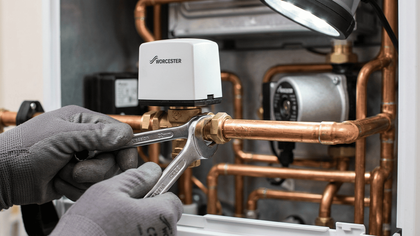
The compression nuts securing the valve to the pipework need careful attention. Use two spanners for each connection. One holds the valve body steady whilst the other 22mm compression spanner turns the nut anticlockwise. This prevents twisting the pipework, which can easily crack standard push fit copper fittings elsewhere in the system.
Installing The New Valve Assembly
Unpack the new Worcester diverter valve assembly V4044F1109 and verify it matches the old unit. Check the port configuration carefully, as the flow and return connections must align exactly with your existing pipework. The valve body has directional arrows indicating flow direction. These must point away from the boiler.
Slide new compression nuts onto the pipe ends, followed by new brass olives. Position the valve body between the pipe ends and hand-tighten both compression nuts. Ensure the motorised actuator mechanism remains accessible for future maintenance. Tighten the nuts firmly using a proper 22mm compression spanner to ensure a secure brass-to-copper seal. Reliable heating valve control relies entirely on these leak-free, correctly torqued connections.
Electrical Connections And Wiring
The Worcester diverter valve assembly V4044F1109 operates on 230V AC and must be wired correctly for safe operation. Incorrect connections can permanently damage the boiler PCB relay or create a severe shock hazard.
Refer to your earlier wiring notes. The live feed provides power to the motor, whilst the neutral completes the circuit. The two switched lives signal the valve position back to the board. Connect each wire to its corresponding terminal, ensuring the spade connectors push fully onto the terminal blades. Loose connections create arcing, which destroys terminals over time. A faulty boiler PCB relay will often result directly from prolonged electrical arcing at a poorly secured valve head.
System Refilling And Testing
With mechanical and electrical connections complete, you are ready to refill and test the system. This process requires patience. Rushing it leads to airlocks and potential pump damage, especially in a modern, highly sensitive combi boiler.
Close all drain cocks and radiator bleed valves. Open the boiler's isolation valves fully. Slowly open both valves on the filling loop and watch the pressure gauge. Fill to the manufacturer's recommended pressure, typically 1.0 to 1.5 bar.
Watch for leaks around the new compression fittings as pressure builds. Restore electrical power at the consumer unit and fused spur. Switch on the boiler and set the programmer to call for heating. You should hear the motor run for 15 to 20 seconds, followed by a distinct click as the microswitch confirms its position.
Troubleshooting Post-Installation Issues
Even with correct installation, you might encounter operational problems. These usually stem from air in the system, incorrect wiring, or faulty components.
If the motor doesn't run when you call for heat, verify the electrical supply at the valve terminals. No voltage indicates a problem upstream. Continuous motor running without stopping points to a missing valve microswitch signal or incorrect wiring.
Both heating and hot water running simultaneously indicates the valve isn't fully diverting flow. This might be air trapped in the valve body preventing complete travel, or mechanical resistance against the motorised actuator mechanism. Try cycling the valve several times between positions to clear any blockages.
Maintenance And Longevity Considerations
The Worcester diverter valve assembly V4044F1109 should provide years of reliable service with minimal maintenance, but certain practices extend its operational life significantly.
Annual servicing should include exercising the valve through several full cycles. During summer months when heating demand is low, the valve can sit in one position for weeks. This allows calcium deposits to build up around the moving parts. Regular operation prevents seizure.
Water quality dramatically affects longevity. Systems with hard water accelerate wear on internal components. A magnetic filter on the system return removes ferrous debris, whilst a scale reducer on the mains cold feed prevents destructive calcium buildup.
Conclusion
The diverter valve assembly represents a critical control point in the heating system. Proper installation technique ensures reliable operation and prevents the callbacks and frustration that come from rushed work. Take your time with the compression nuts, verify the wiring thoroughly before energising the system, and test both cycles before considering the job complete.
The investment in quality tools and proper preparation always pays dividends. A clean pipe slice gives you cuts that seal the first time. A good multimeter verifies electrical connections and diagnoses faults across the entire system. When you need assistance identifying the correct replacement parts for your specific boiler model, contact our technical team to ensure you secure the right components instantly.