
Worcester Gas Valve VK4105M Assembly: Replacement And Calibration Guide
The Worcester gas valve VK4105M assembly sits at the heart of thousands of boilers across the UK, quietly regulating gas flow and flame modulation until it simply doesn't. When this component fails, you are not dealing with a simple swap-and-go situation like changing a standard thermocouple. You are handling a critical safety device that requires proper calibration, precise installation, and a clear understanding of how modern modulating gas valves actually work.
Industry experience highlights the massive difference between a properly calibrated valve and one that has just been bolted into place. The first one runs efficiently, modulates smoothly, and keeps the boiler cycling correctly. The second one guarantees a callback in three months for nuisance lockouts, poor modulation, or far worse. This guide walks through the complete replacement and calibration process, covering everything from initial diagnosis to final commissioning checks. It is not a quick job, but it is one that needs doing right.
Understanding The VK4105M Gas Valve Assembly
This unit isn't just a simple on/off valve. It is a highly complex modulating assembly that controls both gas flow and flame characteristics based on signals from the boiler's control board. Sourcing genuine, factory-calibrated components through Heating and Plumbing World ensures you install hardware designed for exact tolerances.
Think of the stepper motor-driven valve acting exactly like a modern car's electronic fuel injection system. Rather than just blindly dumping fuel into the cylinder, it precisely meters the gas delivery to match the exact heating demand, ensuring maximum efficiency and preventing wasted energy.
This assembly combines several vital functions in one unit:
- Gas flow regulation through a highly precise stepper motor-driven valve mechanism
- Safety shut-off via a reliable dual solenoid shut-off that closes instantly if the flame is lost
- Pressure regulation to maintain a consistent gas feed directly to the main burner
- Modulation control responding seamlessly to the incoming valve modulation signal from the PCB
Diagnosing VK4105M Failure
Before you order a replacement Worcester gas valve VK4105M assembly, confirm you are actually dealing with a mechanical failure rather than a control board issue or wiring problem.
On a recent commercial contract, an apprentice replaced three gas valves on the exact same boiler before realising the main board was actually sending an incorrect valve modulation signal. That misdiagnosis cost the firm hundreds in wasted boiler replacement parts and completely destroyed their profit margin for the day. You must verify your electrical inputs first.
Check these points immediately:
- Verify the 230V supply is reaching the valve connector when the boiler calls for heat
- Measure the valve modulation signal voltage, which should vary between 0V and 10V during operation
- Listen for the characteristic clicking sound when the valve opens
- Inspect the wiring harness for damage, corrosion, or loose connections
Tools And Materials Required
Proper preparation prevents disastrous problems. Gather everything before you start rather than discovering you need a specific tool halfway through the job with the gas supply fully isolated.
Essential tools include a standard gas-safe registered engineer's toolkit, a calibrated flue gas analyser probe for combustion testing, and a multimeter capable of measuring DC voltage and resistance. You also need a dedicated manometer for measuring gas pressure. Never substitute high-pressure gas connections with a standard water push fit joint, as the pressure ratings are completely incompatible.
Isolation And Safe Removal Procedure
Safety comes first, second, and third when working with gas appliances. The valve controls the primary fuel supply to the burner, making proper isolation absolutely critical.
Turn off the boiler at the control panel and isolate the electrical supply at the fused spur. Close the main heating valve control serving the gas supply pipe before the boiler. Allow the unit to cool completely if it has been running. Relieve any residual gas pressure by briefly opening then closing the isolation valve.
Disconnect the electrical connector from the assembly carefully. These connectors usually have a locking tab that must be pressed before the connector pulls free. Don't force it. A broken connector means additional parts and infuriating delays.
Installing The Replacement VK4105M Assembly
The new Worcester gas valve VK4105M assembly should be an exact replacement with identical mounting points and connection types. Handle these precision heating system components carefully, as dropping a valve body can permanently misalign the delicate stepper motor-driven valve inside.
Position the new unit in the mounting location, aligning the inlet and outlet ports perfectly. The valve body should sit flush against the mounting surface without gaps. Install the mounting screws finger-tight initially. You want some adjustment freedom until all connections are made. Connect the valve outlet to the burner manifold using a brand new sealing washer. Tighten the connection firmly, but don't overtighten it. You are compressing a washer, not welding steel.
Gas Tightness Testing
Before you even think about calibration, confirm every single connection is utterly gas-tight. Treat this with the exact same rigor as routine expansion vessel testing on the wet side of the system. A leak at the valve assembly creates an immediate danger and makes accurate calibration utterly impossible.
Open the gas isolation valve slowly and listen for hissing. The absence of an obvious sound doesn't mean you are leak-free, as some leaks remain completely silent at low pressure. Apply leak detection fluid to the valve inlet, the outlet connection, and the valve body itself. Watch for tiny bubbles forming in the detection fluid. Even microscopic bubbles indicate a leak that must be corrected immediately.
Initial Electrical Checks
With gas tightness confirmed, verify electrical operation before attempting calibration. Restore electrical power to the boiler at the fused spur. Initiate a heat demand via the main temperature control system and listen carefully.
You should hear the unit click sharply as the dual solenoid shut-off mechanisms open. If you hear absolute silence, check the control signals from the PCB. Measure the incoming valve modulation signal at the appropriate pins. During initial firing, this should sit around 8V to 10V for maximum rate. As the boiler satisfies the demand, the voltage should drop toward zero.
Combustion Analysis And Calibration
Here is where the job separates competent engineers from cowboys. Proper calibration requires accurate combustion analysis at both maximum and minimum modulation rates.
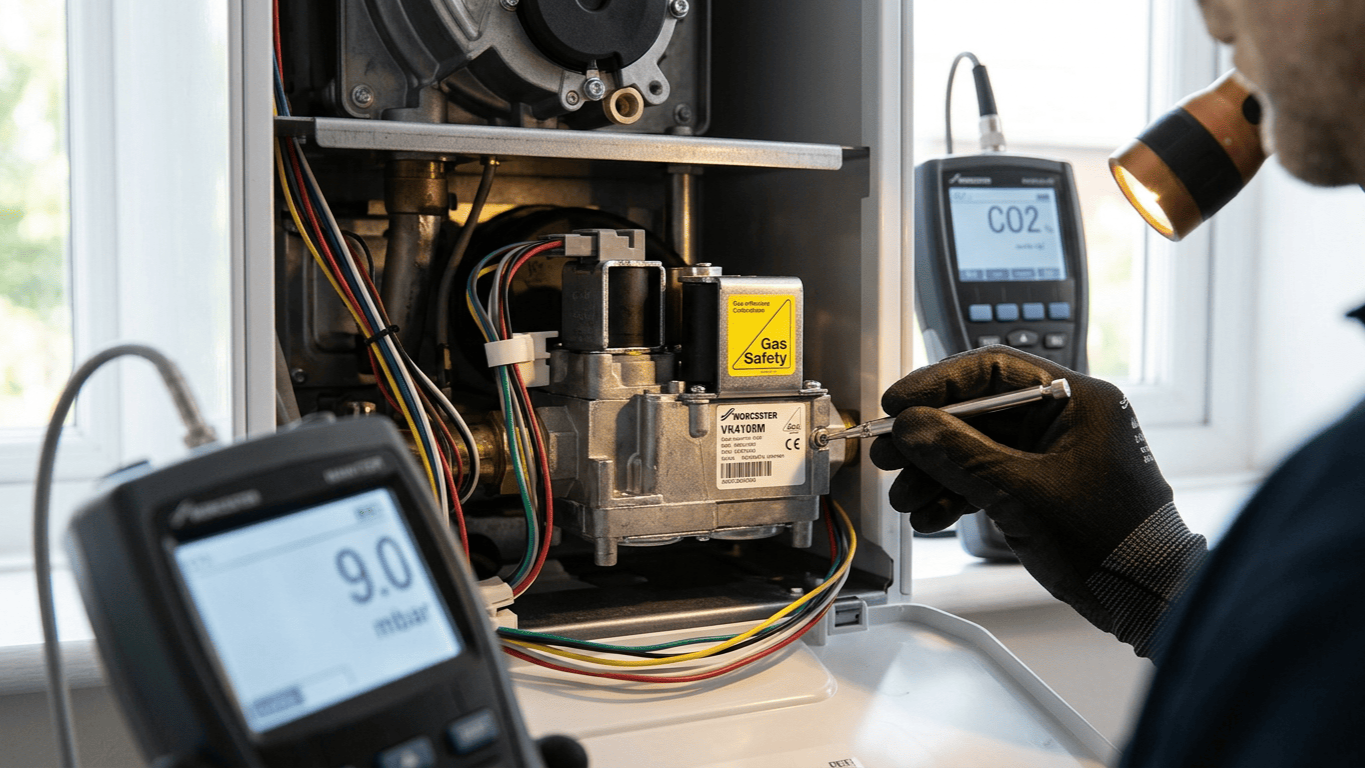
Insert your flue gas analyser probe into the flue according to the manufacturer's instructions. Allow the analyser to warm up and zero properly. Rushed readings produce dangerous calibration errors. Initiate maximum rate firing by setting the boiler to full demand. Allow the boiler to stabilize at maximum rate for at least two minutes before logging data with your flue gas analyser probe.
Record your CO2 percentage, O2 percentage, and CO levels. If the CO2 sits outside the target range, adjust the gas pressure at the valve's pressure test point. Turn the adjustment screw clockwise to increase gas pressure, or anticlockwise to decrease it. Make tiny adjustments, as a simple quarter-turn significantly affects combustion. After calibrating the high fire rate, force the Worcester gas valve VK4105M assembly to its minimum rate and verify the combustion remains safe.
Verifying Modulation Performance
The stepper motor-driven valve should modulate smoothly through its entire range without hunting, sticking, or erratic behaviour. Testing this requires observing the boiler through several complete cycles.
Watch the flame through the viewing window during modulation. You should see smooth transitions between high and low fire without sudden jumps or flame instability. Monitor the valve modulation signal voltage while observing flame behaviour. The flame intensity should track the voltage changes perfectly.
Final Commissioning Checks
You aren't finished until you complete full commissioning checks and document the results. Test the combi boiler through a normal shutdown, ensuring no error codes appear. Verify the dual solenoid shut-off closes completely when the boiler shuts down, checking that zero gas flows at the meter.
Document your combustion readings, gas pressure settings, and any adjustments made. This record proves you completed the work to the legally required standard and provides an invaluable baseline for future service visits.
Common Calibration Problems And Solutions
Even highly experienced engineers occasionally encounter calibration challenges with the Worcester gas valve VK4105M assembly. Knowing the common issues saves diagnostic time.
High carbon monoxide at maximum rate usually indicates insufficient combustion air or a dirty burner. Poor modulation range where the valve seems to operate at only high or low fire suggests severe control signal problems. Flame instability at low fire often points to minimum gas pressure being set too low. Valve cycling where the unit repeatedly opens and closes during a heat demand indicates either incorrect calibration or a control system fault.
Conclusion
Replacing and calibrating a modulating gas valve isn't a job for shortcuts or guesswork. It is precision work that directly affects boiler safety, efficiency, and reliability. The unit must be installed correctly, all connections must be gas-tight, and combustion must be properly calibrated at both extremes.
A properly calibrated valve modulates smoothly, maintains efficient combustion throughout its range, and provides years of exceptionally reliable service. Take the time to complete every step properly and document your work thoroughly. If you require advanced diagnostic parts or replacement components, get expert advice to ensure your next commercial boiler repair is compliant, efficient, and utterly safe.